1800-A: Difference between revisions
No edit summary |
No edit summary |
||
| Line 30: | Line 30: | ||
While several popular General Radio VTVMs preceded and followed the Type 1800, this classic was probably the most famous. | While several popular General Radio VTVMs preceded and followed the Type 1800, this classic was probably the most famous. | ||
It was announced in 1946 and designed by C. E. Woodward with suggestions from | It was announced in 1946 and designed by C. E. Woodward with suggestions from [[Donald B. Sinclair]] who later became a GR President. | ||
It measured both AC and DC voltages over wide voltage ranges and its rectifying probe allowed useful measurements to over 300 MHz. | It measured both AC and DC voltages over wide voltage ranges and its rectifying probe allowed useful measurements to over 300 MHz. | ||
Latest revision as of 20:08, 25 July 2024
The General Radio 1800-A Vacuum-Tube Voltmeter was introduced in Catalog L (1948) and remained available through Catalog N (1954).
The Type 1800-A is a high impedance, high frequency voltmeter. It was designed to replace the 726-A peak-reading voltmeter.
Two range extension accessories were available, the Types 1800-P2 High-Frequency Multiplier, and the 1800-P3 Low-Frequency Multiplier.
On the AC voltage ranges, except for the two lowest, the 1800-A is essentially a peak-reading instrument, but the scales are calibrated to give readings of RMS values of sinusoidal voltages. The upper frequency limit approaches 500 MHz with corrections, approximately 100 MHz without.
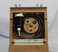
For DC measurements, binding posts are provided along with a shorting strip for the open grid mode. For AC measurements, a hard-wired UHF probe is provided, stored in the top compartment along with its accessories. When in the storage position, the probe plugs into the front panel binding posts where low frequency AC measurements are made. When UHF measurements are desired, the probe is removed for direct connection, the nose piece can be removed to reduce probe capacitance. Also located in the top compartment is a 50 Ω disk resistor used to convert the probe impedance, along with adapters for GR Type 274 and GR Type 874 coaxial connectors.
The 1800-A utilizes two RCA type 9005 "Acorn" UHF diodes (see data sheet below).
https://www.ietlabs.com/genrad_history/genrad_museum says
While several popular General Radio VTVMs preceded and followed the Type 1800, this classic was probably the most famous.
It was announced in 1946 and designed by C. E. Woodward with suggestions from Donald B. Sinclair who later became a GR President.
It measured both AC and DC voltages over wide voltage ranges and its rectifying probe allowed useful measurements to over 300 MHz.
Specifications
- Voltage Range: 0.1 to 150 V AC in 6 ranges; 0.01 to 150 V DC in 6 ranges
- Accuracy: DC and AC ±2% of full scale on 6 ranges; AC accuracy is for sinusoidal voltages
- Input Impedance: at low frequencies AC input resistance 25 MΩ; higher frequencies see manual; DC input resistance is 10 MΩ or open grid, selectable
Links
- Experimenter September 1946 describing Type 1800-A
- Experimenter May 1948 describing Type 1800-P2
- General Radio 1800-P3 Low-Frequency Multiplier Data Sheet 700-C 1954
- Experimenter December 1948 describing Type 1800-P3
- RCA 991 Voltage Regulator Data Sheet 1939
- RCA 9005 UHF Diode Data Sheet 1942


