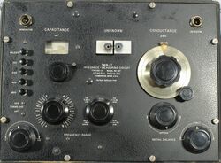
821-A
The General Radio 821-A Twin-T Impedance Measuring Circuit were introduced in Catalog K2 (1942) and remained available through Catalog O (1956).
The Type 821-A is an impedance measuring device operating between 460 kHz and 40 Mhz. Measurements are made using the Parallel-T null circuit and the parallel substitution method.
The 821-A is calibrated in capacitance and conductance. Just some of the applications are the measurement of capacitance and dissipation factor of capacitors, and the inductance and Q of coils. It is best suited for measuring high impedances in contrast to its contemporary, the 916-A RF bridge, which is more suited for lower impedance measurements.
The 821-A requires a generator and detector to accomplish a null. An oscillator of sufficient output at the frequency of interest, the [[1330-A|Type 1330-A Bridge Oscillator] is the recommended generator. A communications type radio receiver equipped with a BFO and RF gain control makes a suitable detector. A well-shielded cable with a coaxial connection to the receiver is highly recommended.
Type 821-A is a direct reading instrument for capacitance and conductance, some math is required to obtain other impedances.
Specifications
- Frequency Range: 460 kHz to 40 MHz
- Conductance Range:
- 0-100 μS at 1 MHz
- 0-300 μS at 3 MHz
- 0-1000 μS at 10 MHz
- 0-3000 μS at 30 MHz
- Accuracy Capacitance: ±1 pF ±0.1%
- Accuracy Conductance: ±0.1% of full scale ±2% of actual dial reading
