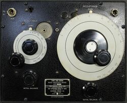
916-A
The General Radio 916-A Radio Frequency Bridge were introduced in Catalog K3 (1944) and remained available through Catalog S (1965).
The Type 916-A Radio Frequency Bridge is designed for impedance measurements at radio frequencies. It can be used to measure directly the reactance and resistance of antennas, transmission lines, or circuit elements.
The bridge uses a circuit similar to the Schering bridge except the 916-A uses the series substitution method of connecting the unknown. Because of its wide frequency range, it requires two types of generator-coupling transformer: Type 916-P1 covers 400 kHz to 3 MHz, and Type 916-P2 covers 3 to 60 MHz. Both transformers were included with the bridge, one installed in the circuit and the other in a storage compartment. Transformers can be replaced using the access cover without removing the instrument from the case.
The 916-A is best suited for measuring low impedances in contrast to its contemporary, the 821-A RF bridge, that is more suited for high-impedance measurements.
The 916-A requires a generator and detector to accomplish a null. An oscillator of sufficient output at the frequency of interest, the Types 1330-A Bridge Oscillator and 1001-A Signal Generator are recommended generators. A communications-type radio receiver equipped with a BFO and RF gain control makes a suitable detector. A well-shielded cable with a coaxial connection to the receiver is highly recommended.
Also available was the Type 916-AL that predated the Type 916-A and was available longer. The 916-AL operates at lower frequencies.
The subject of this article is the Military version CAG-60094 which is identical the the Type 916-A.
Specifications
- Frequency Range: 400 kHz to 60 MHz
- Reactance Range: 5000 Ω at 1 MHz, This range varies inversely as the frequency, and at other frequencies the dial reading must be divided by the frequency in megacycles
- Resistance Range: 0 to 1000 Ω
- Accuracy: For reactance, ±2% ±1 Ω. For resistance, ±1% ±O.l Ω


