650-A: Difference between revisions
No edit summary |
No edit summary |
||
| (8 intermediate revisions by 2 users not shown) | |||
| Line 1: | Line 1: | ||
The 650-A is an impedance | {{GR Product | ||
|model=650-A | |||
|codes=BEAST | |||
|class=impedance measurement | |||
|summary=Impedance Bridge | |||
|image=GR 650-A Close-Up.jpg | |||
|caption=General Radio 650-A Impedance Bridge | |||
|series=650 | |||
|introduced=1934 | |||
|discontinued=1956 | |||
|designers= | |||
|manuals= | |||
* [[Media:GR 650-A Impedance Bridge Manual 346-B.pdf|General Radio 650-A Impedance Bridge Manual 346-B]] | |||
* [[Media:GR 650-A an 650-P1 Impedance Bridge Manual 346-I 01_1962.pdf|General Radio 650-A and 650-P1 Impedance Bridge Manual 346-I 1962]] | |||
{{Catalog History}} | |||
}} | |||
The {{Title|General Radio 650-A Impedance Bridge}} was introduced in {{Catalog G2}} and remained available through {{Catalog O}}. | |||
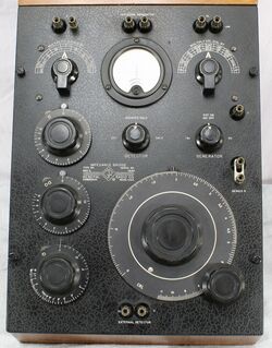
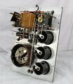
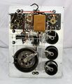
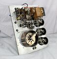
The Type 650-A is a CRL impedance bridge with a basic measurement accuracy between 1% and 2%. Its a self contained battery operated null instrument with an internal AC generator and DC potential. The internal AC generator is the microphone hummer Type [[572-B]] powered by four six inch dry cell batteries. The DC test potential is derived from same series of batteries located in a compartment at the back of the copper lined walnut case. Inductance and capacitance is measured in six ranges and resistance in seven ranges. Measurements are made using three bridge circuits, the Wheatstone, Hay and Maxwell. The recommended detector is a pair of high-impedance headphones for AC measurements. A panel galvanometer with a switchable shunt is used for DC nulls. | |||
An accessory Type [[650-P1]] Oscillator-Amplifier is available providing a 1 kHz generator and a detector amplifier. See the Type [[650-P1]] for details. | |||
Frederick Van Veen [https://www.ietlabs.com/pdf/GR_books/The%20General%20Radio%20Story,%20van%20Veen.pdf writes]: | |||
<blockquote>The most noteworthy introduction of 1933 was the Type 650-A Impedance Bridge, the work of GR engineers Horton and Field. | |||
Priced at $175<sup>1</sup>, the 650 was one of the most successful instruments in the Company’s history, remaining in the GR catalog for the next quarter century. | |||
</blockquote> | |||
==Specifications== | |||
* '''Resistance:''' .001 Ω to 1 MΩ in seven ranges | |||
* '''Capacitance"''' 1 pF to 100 μF in six ranges | |||
* '''Dissipation Factor:''' .002 to 1 in two ranges | |||
* '''Inductance:''' 1 μH to 1 H in six ranges | |||
* '''Storage Factor:''' .02 to 1000 in two ranges | |||
* '''Basic Accuracy:''' 1% to 2% see manual | |||
* '''AC Test Frequency:''' 1 kHz | |||
==Links== | |||
* [[Media:GR Exp 650-A 04_1933.pdf|Experimenter April 1933 describing Type 650-A]] | |||
* [[Media:GR Exp 650-A 09_1944.pdf|Experimenter September 1944 describing Type 650-A]] | |||
* [[Media:GR Exp 650-A 04_1945.pdf|Experimenter April 1945 describing Type 650-A]] | |||
* [[Media:GR Exp 650-P1 04_1946.pdf|Experimenter October 1946 describing Type 650-P1]] | |||
* [[Media:ARC Article GR 650 July 2002.pdf|Antique Radio Classified article July 2002]] | |||
* [https://digital.sciencehistory.org/works/jm214p20f General Radio Type 650-A Impedance Bridge] @ Science and History Institute Museum Digital Collection | |||
<sup>1</sup>About $4,100 in 2023 dollars | |||
==Photos== | |||
<gallery> | |||
GR 650-A Front.jpg | |||
GR 650-A Front A.jpg | |||
GR 650-A Left Side.jpg | |||
GR 650-A Top.jpg | |||
GR 650-A Right.jpg | |||
GR 650-A Case Empty.jpg | |||
GR 650-A Bottom.jpg | |||
GR 650-A Inside Left.jpg | |||
GR 650-A Inside Rear.jpg | |||
GR 650-A Inside Right.jpg | |||
GR 650-A Inside Top.jpg | |||
GR 650-A Inside Center.jpg | |||
GR 650-A Inside Bottom Right.jpg | |||
</gallery> | |||
[[Category:Impedance measurement]] | [[Category:Impedance measurement]] | ||
Latest revision as of 05:17, 3 August 2024
The General Radio 650-A Impedance Bridge was introduced in Catalog G2 (1934) and remained available through Catalog O (1956).
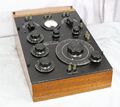
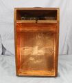
The Type 650-A is a CRL impedance bridge with a basic measurement accuracy between 1% and 2%. Its a self contained battery operated null instrument with an internal AC generator and DC potential. The internal AC generator is the microphone hummer Type 572-B powered by four six inch dry cell batteries. The DC test potential is derived from same series of batteries located in a compartment at the back of the copper lined walnut case. Inductance and capacitance is measured in six ranges and resistance in seven ranges. Measurements are made using three bridge circuits, the Wheatstone, Hay and Maxwell. The recommended detector is a pair of high-impedance headphones for AC measurements. A panel galvanometer with a switchable shunt is used for DC nulls.
An accessory Type 650-P1 Oscillator-Amplifier is available providing a 1 kHz generator and a detector amplifier. See the Type 650-P1 for details.
Frederick Van Veen writes:
The most noteworthy introduction of 1933 was the Type 650-A Impedance Bridge, the work of GR engineers Horton and Field.
Priced at $1751, the 650 was one of the most successful instruments in the Company’s history, remaining in the GR catalog for the next quarter century.
Specifications
- Resistance: .001 Ω to 1 MΩ in seven ranges
- Capacitance" 1 pF to 100 μF in six ranges
- Dissipation Factor: .002 to 1 in two ranges
- Inductance: 1 μH to 1 H in six ranges
- Storage Factor: .02 to 1000 in two ranges
- Basic Accuracy: 1% to 2% see manual
- AC Test Frequency: 1 kHz
Links
- Experimenter April 1933 describing Type 650-A
- Experimenter September 1944 describing Type 650-A
- Experimenter April 1945 describing Type 650-A
- Experimenter October 1946 describing Type 650-P1
- Antique Radio Classified article July 2002
- General Radio Type 650-A Impedance Bridge @ Science and History Institute Museum Digital Collection
1About $4,100 in 2023 dollars
