1025-A: Difference between revisions
(→Photos) |
m (Tidy gallery wiki code) |
||
| (20 intermediate revisions by 2 users not shown) | |||
| Line 1: | Line 1: | ||
{{GR Product | {{GR Product | ||
|model=1025-A | |model=1025-A | ||
|codewords= | |||
|class=oscillators | |class=oscillators | ||
|summary= | |summary=Sweep generator | ||
|image=GR 1025-A Front.jpg | |image=GR 1025-A Front.jpg | ||
|caption=General Radio 1025-A Sweep Frequency Generator | |caption=General Radio 1025-A Sweep Frequency Generator | ||
|series= | |series= | ||
|introduced=1963 | |introduced=1963 | ||
|discontinued= | |discontinued=1968 | ||
|designers=W. F. Byers | |designers=W. F. Byers,Eduard Karplus,E. Favre,D. Foss,W. Montague | ||
|manuals= | |manuals= | ||
* [[Media:GRwiki 1025-A Generator 1025-0110-B 1965.pdf|General Radio 1025-A Sweep Frequency Generator Manual 1025-0110-B 1965]] | * [[Media:GRwiki 1025-A Generator 1025-0110-B 1965.pdf|General Radio 1025-A Sweep Frequency Generator Manual 1025-0110-B 1965]] | ||
{{Catalog History}} | |||
}} | }} | ||
The | The {{Title|General Radio 1025-A Sweep Frequency Generator}} was introduced in {{Catalog R}} and remained available through {{Catalog T}}. | ||
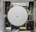
Its frequency-determining variable capacitor rotor is motor-driven. Also mounted on the rotor is a trigger used to create a marker for the swept frequency. | |||
The oscillator covers 0.7 to 230 MHz plus two band spread segments. | |||
The segments on this particular unit are 400 to 500 kHz for broadcast radio IF frequency, and 10.7 MHz ±300 kHz for FM and TV broadcast IF frequencies. | |||
Other custom band spread segments were available. There's also a control to manually turn the rotor to set up the sweep characteristics. | |||
==Specifications== | ==Specifications== | ||
* '''Frequency Range:''' 0.7 to 230 MHz in 10 ranges plus | * '''Frequency Range:''' 0.7 to 230 MHz in 10 ranges plus band spread ranges | ||
* '''Calibration Accuracy:''' At output voltages less than 0.3 volt, frequency is indicated to within +0.5% | * '''Calibration Accuracy:''' At output voltages less than 0.3 volt, frequency is indicated to within +0.5% | ||
* '''Drift:''' Not greater than 0.3% for five hours after one-hour warmup | * '''Drift:''' Not greater than 0.3% for five hours after one-hour warmup | ||
* '''Sweeping Rate:''' 22.2 milliseconds 20 times per second | * '''Sweeping Rate:''' 22.2 milliseconds 20 times per second | ||
==Links== | ==Links== | ||
| Line 30: | Line 37: | ||
GR 1025-A Left Side B.jpg | GR 1025-A Left Side B.jpg | ||
GR 1025-A Left Side.jpg | GR 1025-A Left Side.jpg | ||
GR 1025-A Left Side C.jpg|Sweep Motor Upper Power Supply Lower | GR 1025-A Left Side C.jpg | Sweep Motor Upper Power Supply Lower | ||
GR 1025-A Upper Left.jpg | GR 1025-A Sweep Drive Motor and Clutch.jpg | Sweep Drive Motor and Clutch Assembly | ||
GR 1025-A Rear left.jpg|Power Supply | GR 1025-A Upper Left.jpg | 200 V regulator (A5) | ||
GR 1025-A Rear Lower Right.jpg | GR 1025-A Rear left.jpg | Power Supply | ||
GR 1025-A Rear Upper Right.jpg | GR 1025-A Rear Lower Right.jpg | Top Side of (A4) board | ||
GR 1025-A Right Side Attenuator.jpg| Attenuator | GR 1025-A Rear Upper Right.jpg | Top Side of (A3) board | ||
GR 1025-A Right Side Board A3.jpg|-150 V regulator and meter circuit (A3) | GR 1025-A Right Side Attenuator.jpg | Attenuator | ||
GR 1025-A Right Side Board A4.jpg|Automatic amplitude-control amplifier (A4) | GR 1025-A Right Side Board A3.jpg | -150 V regulator and meter circuit (A3) | ||
GR 1025-A Right Side Board A4.jpg | Automatic amplitude-control amplifier (A4) | |||
GR 1025-A Power Supply Close-up.jpg | Power Supply Board (A8) | |||
GR 1025-A Rear Shield A.jpg | Band Switch Turret and Variable Capacitor Shield Removed | |||
GR 1025-A Rear Shield Band Turret.jpg | Band Switch Turret | |||
GR 1025-A Motorized Variable Capacitor.jpg | Motorized Tuning Capacitor | |||
GR 1025-A Oscillator Close-up.jpg | Oscillator Close-up 5675 Triode Vacuum Tube | |||
</gallery> | </gallery> | ||
[[Category:Oscillators]] | [[Category:Oscillators]] | ||
Latest revision as of 19:16, 22 September 2024
The General Radio 1025-A Sweep Frequency Generator was introduced in Catalog R (1963) and remained available through Catalog T (1968).
Its frequency-determining variable capacitor rotor is motor-driven. Also mounted on the rotor is a trigger used to create a marker for the swept frequency. The oscillator covers 0.7 to 230 MHz plus two band spread segments. The segments on this particular unit are 400 to 500 kHz for broadcast radio IF frequency, and 10.7 MHz ±300 kHz for FM and TV broadcast IF frequencies. Other custom band spread segments were available. There's also a control to manually turn the rotor to set up the sweep characteristics.
Specifications
- Frequency Range: 0.7 to 230 MHz in 10 ranges plus band spread ranges
- Calibration Accuracy: At output voltages less than 0.3 volt, frequency is indicated to within +0.5%
- Drift: Not greater than 0.3% for five hours after one-hour warmup
- Sweeping Rate: 22.2 milliseconds 20 times per second
Links
Photos
-
-
-
-
-
-
Sweep Motor Upper Power Supply Lower
-
Sweep Drive Motor and Clutch Assembly
-
200 V regulator (A5)
-
Power Supply
-
Top Side of (A4) board
-
Top Side of (A3) board
-
Attenuator
-
-150 V regulator and meter circuit (A3)
-
Automatic amplitude-control amplifier (A4)
-
Power Supply Board (A8)
-
Band Switch Turret and Variable Capacitor Shield Removed
-
Band Switch Turret
-
Motorized Tuning Capacitor
-
Oscillator Close-up 5675 Triode Vacuum Tube


