804-B: Difference between revisions
No edit summary |
No edit summary |
||
| Line 18: | Line 18: | ||
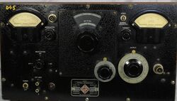
The Type 804-B is a UHF signal generator designed for radio receiver servicing. It covers 7.5 to 330 MHz in five ranges and a user defined sixth range, a blank coil form is supplied with the instrument. With the use of the carrier level meter and attenuator, calibrated levels from 0 to 20 μV are achieved. Front panel switch selects AM modulation of 400 Hz, external modulation or modulation disabled. Caution should be used as there is incidental FM present, particularly at higher frequencies. The vacuum tube used for the oscillator is an RCA "Acorn" type 955 triode. The 804-B uses the Type 774 coaxial connector for carrier output. | The Type 804-B is a UHF signal generator designed for radio receiver servicing. It covers 7.5 to 330 MHz in five ranges and a user defined sixth range, a blank coil form is supplied with the instrument. With the use of the carrier level meter and attenuator, calibrated levels from 0 to 20 μV are achieved. Front panel switch selects AM modulation of 400 Hz, external modulation or modulation disabled. Caution should be used as there is incidental FM present, particularly at higher frequencies. The vacuum tube used for the oscillator is an RCA "Acorn" type 955 triode. The 804-B uses the Type 774 coaxial connector for carrier output. | ||
Note: The undocumented Type 804-C pictures are used for this article. | Note: The undocumented Type 804-C pictures are used for this article. A schematic for the 804-C is located at the rear of the 804-B manual. | ||
==Specifications== | ==Specifications== | ||
Revision as of 05:38, 20 May 2024
The General Radio 804-B UHF Signal Generator was available in Catalog K2 (1942) only.
The Type 804-B is a UHF signal generator designed for radio receiver servicing. It covers 7.5 to 330 MHz in five ranges and a user defined sixth range, a blank coil form is supplied with the instrument. With the use of the carrier level meter and attenuator, calibrated levels from 0 to 20 μV are achieved. Front panel switch selects AM modulation of 400 Hz, external modulation or modulation disabled. Caution should be used as there is incidental FM present, particularly at higher frequencies. The vacuum tube used for the oscillator is an RCA "Acorn" type 955 triode. The 804-B uses the Type 774 coaxial connector for carrier output.
Note: The undocumented Type 804-C pictures are used for this article. A schematic for the 804-C is located at the rear of the 804-B manual.
Specifications
- Frequency Range: 7.5 to 330 MHz in 5 ranges and a sixth user defined range
- Frequency Calibration: direct reading within 2%
- Output Voltage Range: 1 to 20 μV for 7.5-100 MHz; 1 to 10 μV for 100-330 MHz
- Output Impedance: 75 Ω
- Modulation: AM internal 400 Hz, 0 to 60%; AM external 100-20,000 Hz, seven volts are required for 50% modulation
Links
- Experimenter November 1939 describing Type 804-A
- Experimenter February 1941 describing Type 804-B
- RCA 955 Acorn Triode Data Sheet
Photos
-
-
-
-
-
-
-
-
-
-
-
-
-
-
-
-
-
-
Oscillator Coil Storage


