1604-B: Difference between revisions
Jump to navigation
Jump to search
No edit summary |
No edit summary |
||
| Line 16: | Line 16: | ||
The {{Title|General Radio 1604-B Comparison Bridge}} was introduced in {{Catalog N}} and remained available through {{Catalog O}}. | The {{Title|General Radio 1604-B Comparison Bridge}} was introduced in {{Catalog N}} and remained available through {{Catalog O}}. | ||
It was designed for sorting, adjusting and comparing two devices at three different frequencies. | |||
Impedance difference | Impedance difference can be measured in two ranges, 5% or 20%, selected by a front panel switch, using a built-in generator and detector equipped with a 2AP1 CRT. | ||
Balance is achieved when the vertical deflection is at a minimum. | |||
Dissipation factor difference is read directly from the dial in one range. | Dissipation factor difference is read directly from the dial in one range. | ||
| Line 27: | Line 26: | ||
==Specifications== | ==Specifications== | ||
* '''Deviation Range:''' Impedance difference, ±5% and ±20%, switched. Dissipation factor difference, ±0.006 at 400 Hz, ±0.015 at 1 kHz, ±0.075 at 5 kHz | * '''Deviation Range:''' Impedance difference, ±5% and ±20%, switched. Dissipation factor difference, ±0.006 at 400 Hz, ±0.015 at 1 kHz, ±0.075 at 5 kHz | ||
* '''Test Frequency:''' 400 Hz, 1 kHz, | * '''Test Frequency:''' 400 Hz, 1 kHz, or 5 kHz within ±3% | ||
* '''Voltage Applied to Unknown:''' Approximately 1 V for impedances above 500 Ω | * '''Voltage Applied to Unknown:''' Approximately 1 V for impedances above 500 Ω, decreasing for lower values of impedance | ||
==Links== | ==Links== | ||
* [[Media:GRwiki Exp 1604-A 12_1952.pdf|Experimenter describing Type 1604-A | * [[Media:GRwiki Exp 1604-A 12_1952.pdf|Experimenter December 1952 describing Type 1604-A]] | ||
* [[Media:GRwiki Exp 1604-B 02_1954.pdf|Experimenter describing Type 1604-B | * [[Media:GRwiki Exp 1604-B 02_1954.pdf|Experimenter February 1954 describing Type 1604-B]] | ||
* Predecessor: [[1604-A]] (1952) | * Predecessor: [[1604-A]] (1952) | ||
* Successor: [[1605-A|General Radio 1605-A Impedance Comparator]] (1956) | * Successor: [[1605-A|General Radio 1605-A Impedance Comparator]] (1956) | ||
Latest revision as of 00:11, 25 April 2024
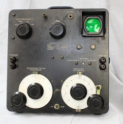
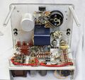
The General Radio 1604-B Comparison Bridge was introduced in Catalog N (1954) and remained available through Catalog O (1956).
It was designed for sorting, adjusting and comparing two devices at three different frequencies.
Impedance difference can be measured in two ranges, 5% or 20%, selected by a front panel switch, using a built-in generator and detector equipped with a 2AP1 CRT. Balance is achieved when the vertical deflection is at a minimum.
Dissipation factor difference is read directly from the dial in one range. The main change from the 1604-A is the addition of a 400 Hz test frequency.
Specifications
- Deviation Range: Impedance difference, ±5% and ±20%, switched. Dissipation factor difference, ±0.006 at 400 Hz, ±0.015 at 1 kHz, ±0.075 at 5 kHz
- Test Frequency: 400 Hz, 1 kHz, or 5 kHz within ±3%
- Voltage Applied to Unknown: Approximately 1 V for impedances above 500 Ω, decreasing for lower values of impedance
Links
- Experimenter December 1952 describing Type 1604-A
- Experimenter February 1954 describing Type 1604-B
- Predecessor: 1604-A (1952)
- Successor: General Radio 1605-A Impedance Comparator (1956)
