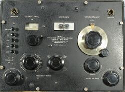
821-A: Difference between revisions
No edit summary |
No edit summary |
||
| Line 1: | Line 1: | ||
{{GR Product | |||
|model=821-A | |||
|codes=LAGER | |||
|class=impedance measurement | |||
|summary=Twin-T Impedance Measuring Circuit | |||
|image=GR 821-A Close-Up.jpg | |||
|caption=General Radio 821-A Twin-T Impedance Measuring Circuit | |||
|series= | |||
|introduced=1942 | |||
|discontinued=1956 | |||
|designers= | |||
|manuals= | |||
* [[Media:GR 821 Twin T Impedance Measuring Circuit 566-D.pdf|General Radio 821-A Twin-T Impedance Measureing Circuit Manual 566-D]] | |||
{{Catalog History}} | |||
}} | |||
The {{Title|General Radio 821-A Twin-T Impedance Measuring Circuit}} were introduced in {{Catalog K2}} and remained available through {{Catalog O}}. | |||
The Type 821-A is an impedance measuring device operating between 460 kHz and 40 Mhz. Measurements are made using the Parallel-T null circuit and the parallel substitution method. Its calibrated in capacitance and conductance. Just some of the applications are the measurement of capacitance and dissipation factor of capacitors, and the inductance and Q of coils. The 821-A requires a generator and detector to accomplish a null. An oscillator of sufficient output at the frequency of interest, the Type [[1330-A]] Bridge Oscillator is the recommended generator. A radio receiver equipped with a BFO and S-Meter makes a suitable detector. A well shielded cable with a coaxial connection to the receiver is highly recommended. | |||
The Type 821-A is direct reading instrument for capacitance and conductance, some math is required to obtain other impedances. | |||
==Specifications== | ==Specifications== | ||
* '''Frequency Range:''' 460 kHz to 40 MHz | |||
* '''Conductance Range:''' | |||
* 0-100 μS at 1 MHz | |||
* 0-300 μS at 3 MHz | |||
* 0-1000 μS at 10 MHz | |||
* 0-3000 μS at 30 MHz | |||
* '''Accuracy Capacitance:''' ±1 pF ±0.1% | |||
* '''Accuracy Conductance:''' ±0.1% of full scale ±2% of actual dial reading | |||
==Links== | ==Links== | ||
* [[Media:GR Exp 821-A 01_1941.pdf|Experimenter January 1941 describing Type 821-A]] | |||
==Photos== | ==Photos== | ||
<gallery> | <gallery> | ||
GR 821-A Front.jpg | |||
GR 821-A Case A.jpg | |||
GR 821-A Case Cover.jpg | |||
GR 821-A Case Top.jpg | |||
GR 821-A Case Ground Side.jpg | |||
GR 821-A Inside Rear.jpg | |||
GR 821-A Inside Rear Left.jpg | |||
GR 821-A Inside Rear Right.jpg | |||
GR 821-A Inside Top.jpg | |||
GR 821-A Indside Rear Lower.jpg | |||
GR 821-A Inside Left A.jpg | |||
GR 821-A Inside Left B.jpg | |||
GR 821-A Inside Left.jpg | |||
GR 821-A Inside Rear Left.jpg | |||
GR 821-A Inside Rear Right.jpg | |||
GR 821-A Inside Right A.jpg | |||
GR 821-A Inside Right Lower.jpg | |||
GR 821-A Inside Right.jpg | |||
</gallery> | </gallery> | ||
[[Category:Impedance measurement]] | [[Category:Impedance measurement]] | ||
Revision as of 18:59, 24 May 2024
The General Radio 821-A Twin-T Impedance Measuring Circuit were introduced in Catalog K2 (1942) and remained available through Catalog O (1956).
The Type 821-A is an impedance measuring device operating between 460 kHz and 40 Mhz. Measurements are made using the Parallel-T null circuit and the parallel substitution method. Its calibrated in capacitance and conductance. Just some of the applications are the measurement of capacitance and dissipation factor of capacitors, and the inductance and Q of coils. The 821-A requires a generator and detector to accomplish a null. An oscillator of sufficient output at the frequency of interest, the Type 1330-A Bridge Oscillator is the recommended generator. A radio receiver equipped with a BFO and S-Meter makes a suitable detector. A well shielded cable with a coaxial connection to the receiver is highly recommended.
The Type 821-A is direct reading instrument for capacitance and conductance, some math is required to obtain other impedances.
Specifications
- Frequency Range: 460 kHz to 40 MHz
- Conductance Range:
- 0-100 μS at 1 MHz
- 0-300 μS at 3 MHz
- 0-1000 μS at 10 MHz
- 0-3000 μS at 30 MHz
- Accuracy Capacitance: ±1 pF ±0.1%
- Accuracy Conductance: ±0.1% of full scale ±2% of actual dial reading


