1607-A: Difference between revisions
(→Photos) |
(→Photos) |
||
| (29 intermediate revisions by 2 users not shown) | |||
| Line 1: | Line 1: | ||
{{GR Product | {{GR Product | ||
|model=1607-A | |model=1607-A | ||
|codes=HYDRA | |||
|class=impedance measurement | |class=impedance measurement | ||
|summary=Transfer-Function and Immittance Bridge | |summary=Transfer-Function and Immittance Bridge | ||
| Line 11: | Line 12: | ||
|manuals= | |manuals= | ||
* [[Media:GR 1607-A Transfer-Function and Immittance Bridge 1607-0100-F 11_1964.pdf|GR 1607-A Transfer-Function and Immittance Bridge Manual 1607-0100-F 1964]] | * [[Media:GR 1607-A Transfer-Function and Immittance Bridge 1607-0100-F 11_1964.pdf|GR 1607-A Transfer-Function and Immittance Bridge Manual 1607-0100-F 1964]] | ||
* [[Media:Condensed Operating Instructions for Type 1607-A.pdf|Condensed Operating Instructions for Type 1607-A 1607-0102-D]] | |||
* [[Media:Transfer-Function and Immittance Bridge Line-Scale Chart.pdf|Transfer-Function and Immittance Bridge Line-Scale Chart]] | |||
{{Catalog History}} | {{Catalog History}} | ||
}} | }} | ||
The {{Title|General Radio 1607-A Transfer-Function and Immittance Bridge}} was introduced in {{Catalog P}} and remained available through {{Catalog U}}. | The {{Title|General Radio 1607-A Transfer-Function and Immittance Bridge}} was introduced in {{Catalog P}} and remained available through {{Catalog U}}. | ||
The Type 1607-A is a null-type instrument designed to measure transfer-functions and immittance at frequencies from 25 MHz to 1.2 GHz using separate indicator units. It can measure passive devices as well as active devices such as semiconductors and vacuum tubes. | |||
An example transfer-function measurement would be the alpha of a transistor at 500 MHz or the immittance of a resistor or network at 1 GHz. Other uses are the measurement of reflection coefficient and VSWR of antennas and transmission lines. | |||
As a bridge instrument, the 1607-A requires an oscillator and DNT or heterodyne type detector operating at the frequency of interest. The theory of operation of the Type 1607-A is similar to the [[1602-B]]. | |||
==Specifications== | ==Specifications== | ||
| Line 24: | Line 31: | ||
==Links== | ==Links== | ||
* [[Media:GR Exp 1607-A | * [[Media:GR Exp 1607-A 03_1958.pdf|Experimenter March 1958 describing Type 1607-A]] | ||
* [[Media:GR Exp 1607-A 05_1959.pdf|Experimenter May 1959 describing Type 1607-A]] | |||
* [[Media:GR Exp 1607-A 07_1960.pdf|Experimenter July 1960 describing Type 1607-A]] | |||
* [[Media:GR Exp 1607-A 02_1965.pdf|Experimenter February 1965 describing Type 1607 Transistor Mounts]] | |||
* [[Media:Handbook of Coaxial Microwave Measurements.pdf|Handbook of Coaxial Microwave Measurements]] | |||
==Photos== | ==Photos== | ||
<gallery> | <gallery> | ||
GR1607 components.jpg | GR1607 components.jpg | ||
GR 1607-A Case Closed.jpg | GR 1607-A Storage Label A.jpg|Late Case Component Locations | ||
GR 1607-A Case Closed.jpg|1607-3130 Storage Box | |||
GR 1607-A Case Cover Open.jpg | GR 1607-A Case Cover Open.jpg | ||
GR 1607-A Case Open Accessories A.jpg | GR 1607-A Case Open Accessories A.jpg | ||
| Line 36: | Line 48: | ||
GR 1607-A Case Cover Storage Center A.jpg | GR 1607-A Case Cover Storage Center A.jpg | ||
GR 1607-A Case Cover Storage Center B.jpg | GR 1607-A Case Cover Storage Center B.jpg | ||
GR 1607-A Immittance Indicator A.jpg | GR 1607-A Immittance Indicator A.jpg|1607-P9 Immittance Indicator | ||
GR 1607-P10 and P11.jpg | GR 1607-P10 and P11.jpg|1607-P10 & 1607-P11 Multiplier Plates | ||
GR 1607-A Case Storage A | GR 1607-A Case Storage A.jpg|1607-P7-Δ/2 21.5-cm Air Line & 874-WO3 874-WO5 Open-Circuit Terminations | ||
GR 1607-A Case Storage Bottom B.jpg | GR 1607-A Case Storage Bottom B.jpg|1607-P5 & 1607-P6 Range Extension Unit and Support | ||
GR 1607-P3 Variable Capacitor.jpg | GR 1607-P3 Variable Capacitor.jpg|1607-P3 Variable Air Capacitor | ||
GR 1607-A Case Storage Bottom.jpg|1607-P7-Δ 43-cm Air Line & 1607-P1 Adjustable Stub | |||
GR 1607-A Case Storage Bottom.jpg | GR 1607-A Front.jpg|1607-3030 Main Instrument | ||
GR 1607-A Front.jpg | GR 1607-A Front Left.jpg|1607-3030 Main Instrument | ||
GR 1607-A Front Left.jpg | GR 1607-A Front Right.jpg|1607-3030 Main Instrument | ||
GR 1607-A Front Right.jpg | GR 1607-A Rear A.jpg|1607-3030 Main Instrument | ||
GR 1607-A Rear A.jpg | GR 1607-A Rear B.jpg|1607-3030 Main Instrument | ||
GR 1607-A Rear B.jpg | GR 1607-A Immittance Indicator B.jpg|1607-P9 Immittance Indicator | ||
GR 1607-A Immittance Indicator B.jpg | GR 1607-A Immittance Indicator C.jpg|1607-P9 Immittance Indicator | ||
GR 1607-A Immittance Indicator C.jpg | GR 1607-A 874-U and 874-U-S2.jpg|874-U and 874-U-S2 U-Line Sections | ||
GR 1607-A Tee P2 and Termination P4 A.jpg | GR 1607-7A_2 874-WO3 874-WO5.jpg|1607-P7-Δ/2 21.5-cm Air Line & 874-WO3 874-WO5 Open-Circuit Terminations | ||
GR 1607-A Tee P2 and Termination P4.jpg | GR 1607-P7-A 1607-P1.jpg|1607-P7-Δ 43-cm Air Line & 1607-P1 Adjustable Stub | ||
GR 1607-P3 Variable Capacitor A.jpg | GR 1607-A Tee P2 and Termination P4 A.jpg|1607-P2 Tee & 1607-P4 Termination | ||
GR 1607-P5 Range Extension Unit.jpg | GR 1607-A Tee P2 and Termination P4.jpg|1607-P2 Tee & 1607-P4 Termination | ||
GR 1607-P8-2A Cable.jpg | GR1607-P2-2.jpg | 1607-P2 | ||
GR 874-20A Cable.jpg | GR1607-P2-3.jpg | 1607-P2 | ||
GR 1607-P8-4A Cable.jpg | GR 1607-P3 Variable Capacitor A.jpg|1607-P3 Variable Air Capacitor | ||
GR 1607-P8-5A Cable.jpg | GR 1607-P5 Range Extension Unit.jpg|1607-P5 & 1607-P6 Range Extension Unit and Support | ||
GR 1607-P8-6A Cable.jpg | GR 1607-P8-2A Cable.jpg|1607-P8-2Δ Patch Cord | ||
GR 874-20A Cable.jpg|874-R20A Patch Cord | |||
GR 1607-P8-4A Cable.jpg|1607-P8-4Δ Patch Cord | |||
GR 1607-P8-5A Cable.jpg|1607-P8-5Δ Patch Cord | |||
GR 1607-P8-6A Cable.jpg|1607-P8-6Δ Patch Cord | |||
</gallery> | </gallery> | ||
[[Category:Impedance measurement]] | [[Category:Impedance measurement]] | ||
Latest revision as of 22:10, 8 July 2024
The General Radio 1607-A Transfer-Function and Immittance Bridge was introduced in Catalog P (1959) and remained available through Catalog U (1970).
The Type 1607-A is a null-type instrument designed to measure transfer-functions and immittance at frequencies from 25 MHz to 1.2 GHz using separate indicator units. It can measure passive devices as well as active devices such as semiconductors and vacuum tubes.
An example transfer-function measurement would be the alpha of a transistor at 500 MHz or the immittance of a resistor or network at 1 GHz. Other uses are the measurement of reflection coefficient and VSWR of antennas and transmission lines.
As a bridge instrument, the 1607-A requires an oscillator and DNT or heterodyne type detector operating at the frequency of interest. The theory of operation of the Type 1607-A is similar to the 1602-B.
Specifications
- Frequency Range: 25 to 1500 MHz, with reduced accuracy above 1000 MHz and when flexible line-extension cables (required below 150 MHz) are used
- Measurement Ranges and Accuracy: See manual
Links
- Experimenter March 1958 describing Type 1607-A
- Experimenter May 1959 describing Type 1607-A
- Experimenter July 1960 describing Type 1607-A
- Experimenter February 1965 describing Type 1607 Transistor Mounts
- Handbook of Coaxial Microwave Measurements
Photos
-
-
Late Case Component Locations
-
1607-3130 Storage Box
-
-
-
-
-
-
-
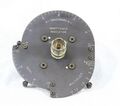
1607-P9 Immittance Indicator
-
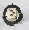
1607-P10 & 1607-P11 Multiplier Plates
-
1607-P7-Δ/2 21.5-cm Air Line & 874-WO3 874-WO5 Open-Circuit Terminations
-
1607-P5 & 1607-P6 Range Extension Unit and Support
-
1607-P3 Variable Air Capacitor
-
1607-P7-Δ 43-cm Air Line & 1607-P1 Adjustable Stub
-
1607-3030 Main Instrument
-
1607-3030 Main Instrument
-
1607-3030 Main Instrument
-
1607-3030 Main Instrument
-
1607-3030 Main Instrument
-
1607-P9 Immittance Indicator
-
1607-P9 Immittance Indicator
-
874-U and 874-U-S2 U-Line Sections
-
1607-P7-Δ/2 21.5-cm Air Line & 874-WO3 874-WO5 Open-Circuit Terminations
-
1607-P7-Δ 43-cm Air Line & 1607-P1 Adjustable Stub
-
1607-P2 Tee & 1607-P4 Termination
-
1607-P2 Tee & 1607-P4 Termination
-
1607-P2
-
1607-P2
-
1607-P3 Variable Air Capacitor
-
1607-P5 & 1607-P6 Range Extension Unit and Support
-
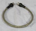
1607-P8-2Δ Patch Cord
-
874-R20A Patch Cord
-
1607-P8-4Δ Patch Cord
-
1607-P8-5Δ Patch Cord
-
1607-P8-6Δ Patch Cord


