740-B: Difference between revisions
Jump to navigation
Jump to search
No edit summary |
No edit summary |
||
| (3 intermediate revisions by 2 users not shown) | |||
| Line 1: | Line 1: | ||
{{GR Product | |||
|model=740-B | |||
|codes=BABEL | |||
|class=impedance measurement | |||
|summary=Capacitance Test Bridge | |||
|image=GR 740-A Close-up.jpg | |||
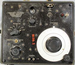
|caption=General Radio GR 740-B Capacitance Test Bridge 497-D | |||
|series= | |||
|introduced=1939 | |||
|discontinued=1961 | |||
|designers= | |||
|manuals= | |||
* '''Manual Needed''' | |||
* [[Media:GR 740-B Capacitance Test Bridge 497-D.pdf|General Radio GR 740-B Capacitance Test Bridge Instruction Sheet 497-D]] | |||
{{Catalog History}} | |||
}} | |||
The {{Title|General Radio 740-B Capacitance Test Bridge}} was introduced in {{Catalog K1}} and remained available through {{Catalog Q}}. | |||
The Type 740-B self contained capacitance bridge designed as a service grade instrument. It's self contained with 60 Hz generator derived from it's power transformer. A 6E5 "Eye" tube is used as the null indicator along with a detector sensitivity control. The voltage impressed upon the unknown varies with range switch setting, 35 volts at .0001 μF and 1 volt at the 100 μF settings. The bridge is suitable for testing of paper, mica, and electrolytic capacitors with 1% accuracy. | |||
==Specifications== | ==Specifications== | ||
* '''Capacitance Range:''' 5 pF to 1100 μF in six ranges | |||
* '''Capacitance Accuracy:''' 1% basic accuracy | |||
* '''Dissipation Range:''' 0 to 50% in two ranges | |||
* '''Dissipation Accuracy:''' 1.5% of full-scale reading for all capacitance multipliers except .0001 range | |||
==Links== | ==Links== | ||
* [[Media:GR Exp 740-B 06_1938.pdf|Experimenter June 1938 describing Type 740-B]] | |||
* [[Media:GR Exp 740-BG 02_1939.pdf|Experimenter February 1939 describing Type 740-BG]] | |||
* [[Media:GR Exp 740-B 09_1942.pdf|Experimenter September 1942 describing Type 740-B]] | |||
==Photos== | ==Photos== | ||
<gallery> | <gallery> | ||
GR 740-A Front.jpg | |||
GR 740-A Cover.jpg | |||
GR 740-A Case Top.jpg | |||
GR 740-A Case Rear.jpg | |||
GR 740-A Case Inside.jpg | |||
GR 740-A Cover Inside.jpg | |||
GR 740-A Instructions.jpg | |||
GR 740-A Schematic Parts List.jpg | |||
GR 740-A Rear Open.jpg | |||
GR 740-A Inside Bottom.jpg | |||
GR 740-A Inside Left.jpg | |||
GR 740-A Inside Right.jpg | |||
GR 740-A Inside Top.jpg | |||
</gallery> | </gallery> | ||
[[Category:Impedance measurement]] | [[Category:Impedance measurement]] | ||
Latest revision as of 10:48, 30 June 2024
The General Radio 740-B Capacitance Test Bridge was introduced in Catalog K1 (1939) and remained available through Catalog Q (1961).
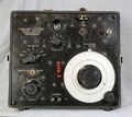
The Type 740-B self contained capacitance bridge designed as a service grade instrument. It's self contained with 60 Hz generator derived from it's power transformer. A 6E5 "Eye" tube is used as the null indicator along with a detector sensitivity control. The voltage impressed upon the unknown varies with range switch setting, 35 volts at .0001 μF and 1 volt at the 100 μF settings. The bridge is suitable for testing of paper, mica, and electrolytic capacitors with 1% accuracy.
Specifications
- Capacitance Range: 5 pF to 1100 μF in six ranges
- Capacitance Accuracy: 1% basic accuracy
- Dissipation Range: 0 to 50% in two ranges
- Dissipation Accuracy: 1.5% of full-scale reading for all capacitance multipliers except .0001 range
Links
- Experimenter June 1938 describing Type 740-B
- Experimenter February 1939 describing Type 740-BG
- Experimenter September 1942 describing Type 740-B


