1650-A: Difference between revisions
Jump to navigation
Jump to search
(replaced BAMA manual link with local OCRed copies, added links) |
No edit summary |
||
| (19 intermediate revisions by the same user not shown) | |||
| Line 1: | Line 1: | ||
The | {{GR Product | ||
|model=1650-A | |||
|codes=BATON,1650-9701,1650-9540,1650-9570 | |||
|class=impedance measurement | |||
|summary=Portable impedance bridge | |||
|image=Gr 1650-a 1.jpeg | |||
|caption=Genrad 1650-A Bridge | |||
|series= | |||
|introduced=1959 | |||
|discontinued=1967 | |||
|designers=Henry P. Hall | |||
|manuals= | |||
* [[Media:GR 1650-A Impedance Bridge Manual (1964).pdf|General Radio 1650-A Impedance Bridge Manual, 1964 version]] (OCRed) | |||
* [[Media:GR 1650-A Impedance Bridge Manual (1960).pdf|General Radio 1650-A Impedance Bridge Manual, 1960 version]] (OCRed) | |||
{{Catalog History}} | |||
}} | |||
The {{Title|General Radio 1650-A}} is a portable impedance bridge introduced in {{Catalog P}}. It was succeeded by the [[1650-B]] in {{Catalog T}}. | |||
The 1650 was the first GR impedance bridge to feature the "Orthonull" function, which is a mechanical link driving the DQ dial from the CRL dial through a friction clutch. (Conversely, turning the DQ dial will ''not'' turn the CRL dial.) | |||
It helps avoid the "sliding null" problem when measuring components with high losses. | |||
The 1650 | The [[1650-P1|1650-P1 Test Jig]] accessory was designed for the 1650-A. | ||
==Specifications== | ==Key Specifications== | ||
* Capacitance: 1 pF to 1100 μF in 7 ranges | * Capacitance: 1 pF to 1100 μF in 7 ranges | ||
* Inductance: 1 μH to 1100 H in 7 ranges | * Inductance: 1 μH to 1100 H in 7 ranges | ||
* Resistance: 1 mΩ | * Resistance: 1 mΩ to 11 MΩ in 8 ranges, AC or DC | ||
* D | * D (of series capacitance): 0.001 to 1 at 1 kHz, (parallel capacitance) 0.1 to 50 at 1 kHz | ||
* Q | * Q (of series inductance): 0.02 to 10 at 1 kHz, (parallel inductance) 1 to 1000 at 1 kHz | ||
* Basic accuracy: ±1% of full scale, ±5% for dissipation factor | * Basic accuracy: ±1% of full scale, ±5% for dissipation factor | ||
* Internal oscillator: 1 kHz ±2% | * Internal oscillator: 1 kHz ±2% | ||
* Frequency range: 20 Hz to 20 kHz (to 100 kHz with reduced accuracy) | * Frequency range: 20 Hz to 20 kHz (to 100 kHz with reduced accuracy) | ||
* DC Supply: 6 V, max. 60 mA; Battery: Four D cells, current drain 10 mA (AC measurements) | |||
* External Oscillator and Detector: [[1210-C|Type 1210-C Unit R-C Oscillator]], [[1311-A|Type 1311-A Audio Oscillator]] and [[1232-A|Type 1232-A Tuned Amplifier and Null Detector]] are recommended for audio measurements at frequencies other than 1 kHz | |||
* [[ | * DC Polarization: 600 V may be applied (from external source) for series capacitance measurements | ||
* Weight: 17 pounds (8 kg) net | |||
==Links== | ==Links== | ||
| Line 22: | Line 40: | ||
* [https://patents.google.com/patent/US2872639A/en US Patent 2872639, Henry P Hall, ''Electrical bridge and method'']. Filed Oct. 10, 1956; Granted Feb. 3, 1959 (describing the Orthonull feature) | * [https://patents.google.com/patent/US2872639A/en US Patent 2872639, Henry P Hall, ''Electrical bridge and method'']. Filed Oct. 10, 1956; Granted Feb. 3, 1959 (describing the Orthonull feature) | ||
* [https://patents.google.com/patent/US2966257A/en US Patent 2966257, Henry C Littlejohn, ''Instrument carrying case'']. Filed Nov. 5, 1959; Granted Dec. 27, 1960 | * [https://patents.google.com/patent/US2966257A/en US Patent 2966257, Henry C Littlejohn, ''Instrument carrying case'']. Filed Nov. 5, 1959; Granted Dec. 27, 1960 | ||
* [[Henry P. Hall]], ''A New Universal Impedance Bridge''. [ | * [[Henry P. Hall]], ''A New Universal Impedance Bridge''. [[Media:General Radio Experimenter Vol.33 No.3 March 1959.pdf|General Radio Experimenter Volume 33, No. 3, March 1959]], page 3. | ||
* [[Henry P. Hall]], ''Orthonull - A Mechanical Device to Improve Bridge Balance Convergence''. [[Media:General Radio Experimenter Vol.33 No.4 April 1959.pdf|General Radio Experimenter Volume 33, No. 4, April 1959]], page 7. | |||
* [https://www.ietlabs.com/pdf/application_notes/12-Henry%20Hall%20Digibridge%20Patent-Digibridge.pdf IET Labs Application Note, ''Henry Hall: Father of the Digibridge''] | * [https://www.ietlabs.com/pdf/application_notes/12-Henry%20Hall%20Digibridge%20Patent-Digibridge.pdf IET Labs Application Note, ''Henry Hall: Father of the Digibridge''] | ||
===Videos=== | |||
* [https://www.youtube.com/watch?v=Id9wMgjEQ04 General Radio Genrad 1650 impedance bridge - Oscillator Circuit repair and calibration] @ YouTube | |||
* [https://www.youtube.com/watch?v=VMFOWfUiLLw General Radio 1650-A Experimentation with Coils Capacitors and Tank circuits] @ YouTube | |||
* [https://www.youtube.com/watch?v=96G_VjkvvnE Vacuum Tube Audio Transformer Impedance Determined With General Radio Impedance Bridge] @ YouTube | |||
==Pictures== | ==Pictures== | ||
| Line 34: | Line 58: | ||
</gallery> | </gallery> | ||
===Internal=== | |||
<gallery> | <gallery> | ||
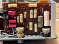
GR 1650-A internal 1.jpg | GR 1650-A internal 1.jpg | Internal view. The red jack on the bottom left is an aftermarket modification on this unit for an external +6 V supply. | ||
GR 1650-A internal 2.jpg | GR 1650-A internal 2.jpg | ||
GR 1650-A internal 3.jpg | GR 1650-A internal 3.jpg | ||
| Line 49: | Line 73: | ||
[[Category:Impedance measurement]] | [[Category:Impedance measurement]] | ||
[[Category:Introduced in 1959]] | [[Category:Introduced in 1959]] | ||
__NOTOC__ | |||
Latest revision as of 02:35, 4 June 2024

The General Radio 1650-A is a portable impedance bridge introduced in Catalog P (1959). It was succeeded by the 1650-B in Catalog T (1968).
The 1650 was the first GR impedance bridge to feature the "Orthonull" function, which is a mechanical link driving the DQ dial from the CRL dial through a friction clutch. (Conversely, turning the DQ dial will not turn the CRL dial.) It helps avoid the "sliding null" problem when measuring components with high losses.
The 1650-P1 Test Jig accessory was designed for the 1650-A.
Key Specifications
- Capacitance: 1 pF to 1100 μF in 7 ranges
- Inductance: 1 μH to 1100 H in 7 ranges
- Resistance: 1 mΩ to 11 MΩ in 8 ranges, AC or DC
- D (of series capacitance): 0.001 to 1 at 1 kHz, (parallel capacitance) 0.1 to 50 at 1 kHz
- Q (of series inductance): 0.02 to 10 at 1 kHz, (parallel inductance) 1 to 1000 at 1 kHz
- Basic accuracy: ±1% of full scale, ±5% for dissipation factor
- Internal oscillator: 1 kHz ±2%
- Frequency range: 20 Hz to 20 kHz (to 100 kHz with reduced accuracy)
- DC Supply: 6 V, max. 60 mA; Battery: Four D cells, current drain 10 mA (AC measurements)
- External Oscillator and Detector: Type 1210-C Unit R-C Oscillator, Type 1311-A Audio Oscillator and Type 1232-A Tuned Amplifier and Null Detector are recommended for audio measurements at frequencies other than 1 kHz
- DC Polarization: 600 V may be applied (from external source) for series capacitance measurements
- Weight: 17 pounds (8 kg) net
Links
- The GR 1650-A & 1650-B Portable Bridges @ conradhoffman.com
- US Patent 2872639, Henry P Hall, Electrical bridge and method. Filed Oct. 10, 1956; Granted Feb. 3, 1959 (describing the Orthonull feature)
- US Patent 2966257, Henry C Littlejohn, Instrument carrying case. Filed Nov. 5, 1959; Granted Dec. 27, 1960
- Henry P. Hall, A New Universal Impedance Bridge. General Radio Experimenter Volume 33, No. 3, March 1959, page 3.
- Henry P. Hall, Orthonull - A Mechanical Device to Improve Bridge Balance Convergence. General Radio Experimenter Volume 33, No. 4, April 1959, page 7.
- IET Labs Application Note, Henry Hall: Father of the Digibridge
Videos
- General Radio Genrad 1650 impedance bridge - Oscillator Circuit repair and calibration @ YouTube
- General Radio 1650-A Experimentation with Coils Capacitors and Tank circuits @ YouTube
- Vacuum Tube Audio Transformer Impedance Determined With General Radio Impedance Bridge @ YouTube
Pictures


Internal
-
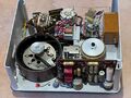
Internal view. The red jack on the bottom left is an aftermarket modification on this unit for an external +6 V supply.
-

-
-
-
-
-
-


