1657: Difference between revisions
Jump to navigation
Jump to search
No edit summary |
(→Photos) |
||
| (4 intermediate revisions by 2 users not shown) | |||
| Line 7: | Line 7: | ||
|series= | |series= | ||
|introduced=1976 | |introduced=1976 | ||
|discontinued= | |discontinued=1978+ | ||
|designers=Henry P. Hall | |designers=Henry P. Hall | ||
|manuals= | |manuals= | ||
| Line 23: | Line 23: | ||
* [https://patents.google.com/patent/US4342089A/en US Patent 4342089, Henry P Hall, ''Method of and apparatus for automatic measurement of circuit parameters with microprocessor calculation techniques'']. Filed Dec 12, 1979; Granted July 27, 1982 | * [https://patents.google.com/patent/US4342089A/en US Patent 4342089, Henry P Hall, ''Method of and apparatus for automatic measurement of circuit parameters with microprocessor calculation techniques'']. Filed Dec 12, 1979; Granted July 27, 1982 | ||
* [https://www.youtube.com/watch?v=Cn4B7ac4lr0 How to measure R, C, L using vintage LCR meter] @ YouTube | * [https://www.youtube.com/watch?v=Cn4B7ac4lr0 How to measure R, C, L using vintage LCR meter] @ YouTube | ||
* Gipe, M.A., Hall, H.P. and Sullivan, R., "Microprocessor Simplifies Impedance Measurements", Session 1, Paper #4, Wescon 1976 | |||
* Hall, H.P., "Analog tests: the microprocessor scores" IEEE Spectrum, April 1977 | |||
* [http://www.tauntek.com/GR1657.htm 1657 description, disassembly and Verilog simulation] @ tauntek.com | |||
==Internals== | ==Internals== | ||
| Line 37: | Line 40: | ||
1657 2.jpg | 1657 2.jpg | ||
1657 3.jpg | 1657 3.jpg | ||
GR 1657 Front.jpg | |||
GR 1657 Front A.jpg | |||
GR 1657 Left.jpg | |||
GR 1657 Rear.jpg | |||
GR 1657 Right.jpg | |||
GR 1657 Top wo_Power Supply Cover.jpg | |||
GR 1657 Top wo_PS and Display.jpg | |||
GR 1657 Power Supply Top.jpg | |||
GR 1657 Power Supply Close-Up.jpg | |||
GR 1657 Display Board Component Side.jpg | |||
GR 1657 Display Board Foil Side.jpg | |||
GR 1657 Main Board Component Side.jpg | |||
GR 1657 Main Board Diagnostic Ports.jpg | |||
GR 1657 Main Board Foil Side.jpg | |||
GR 1657 20uf Electrolytic Measurement.jpg | |||
GR 1657 33 Ohm Measurement.jpg | |||
</gallery> | </gallery> | ||
Latest revision as of 05:06, 30 May 2024
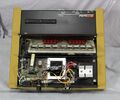
The General Radio 1657 Digibridge is a digital RLC meter, introduced in 1976 1.
Specifications
please add
Links
- Henry P. Hall
- US Patent 4342089, Henry P Hall, Method of and apparatus for automatic measurement of circuit parameters with microprocessor calculation techniques. Filed Dec 12, 1979; Granted July 27, 1982
- How to measure R, C, L using vintage LCR meter @ YouTube
- Gipe, M.A., Hall, H.P. and Sullivan, R., "Microprocessor Simplifies Impedance Measurements", Session 1, Paper #4, Wescon 1976
- Hall, H.P., "Analog tests: the microprocessor scores" IEEE Spectrum, April 1977
- 1657 description, disassembly and Verilog simulation @ tauntek.com
Internals
The 1657 applies a sine wave to the measured device and a precision resistor in series. The average voltage across each is measured using four different phases relative to the input sine wave, for a total of eight measurements. From these, the resistive and reactive components of the tested device are calculated and displayed.
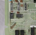
The 1657 uses a 6503 CPU, which is a 28-pin version of the 6502 with the same instruction set, but fewer address lines. The 1657's firmware is contained in a 2Kx8 ROM, in later versions a 2716 EPROM. A 128-byte SRAM holds scratchpad and the stack.
Photos


