1750-A: Difference between revisions
(→Photos) |
No edit summary |
||
| (One intermediate revision by one other user not shown) | |||
| Line 16: | Line 16: | ||
The {{Title|General Radio 1750-A Sweep Drive}} was introduced in {{Catalog O}} and remained available through {{Catalog T}}. | The {{Title|General Radio 1750-A Sweep Drive}} was introduced in {{Catalog O}} and remained available through {{Catalog T}}. | ||
The Type 1750-A sweep drive is designed to mechanically sweep an oscillator through a flexible universal coupling. The sweep action is reciprocating motion of the attached oscillator's frequency control. Front panel controls for sweep arc, sweep speed, manual rotation. The sweep drive provides two synchronized circuits, a horizontal voltage for oscilloscope deflection and a blanking circuit which eliminates the return trace. With the mechanical sweep and the auxiliary circuits | The Type 1750-A sweep drive is designed to mechanically sweep an oscillator through a flexible universal coupling. The sweep action is reciprocating motion of the attached oscillator's frequency control. | ||
Front-panel controls are available for sweep arc, sweep speed, and manual rotation. | |||
The sweep drive provides two synchronized circuits, a horizontal voltage for oscilloscope deflection, and a blanking circuit which eliminates the return trace. | |||
With the mechanical sweep and the auxiliary circuits, an oscilloscope display is possible. | |||
For every cycle of the oscillator sweep, a blanking signal and horizontal deflection voltage are created. | |||
The blanking signal is produced by a synchronized, cam-operated blanking switch. | |||
The synchronized oscilloscope horizontal voltage is produced by the oscilloscope deflection rheostat. | |||
A set of limit switches are designed to stop the sweep motor if the limits are exceeded. One limit is fixed, the other is adjustable. | |||
A system comprising the 1750-A sweep drive, an oscillator, and oscilloscope are used to create a spectrum display for the device of interest. The device can be a filter, amplifier, network or radio receiver. | A system comprising the 1750-A sweep drive, an oscillator, and oscilloscope are used to create a spectrum display for the device of interest. The device can be a filter, amplifier, network or radio receiver. | ||
Not all oscillators are compatible with the 1750-A, check | Not all oscillators are compatible with the 1750-A, check the oscillator manual for compatibility. | ||
==Specifications== | ==Specifications== | ||
| Line 38: | Line 44: | ||
* '''Sweep Voltage:''' 2.5 V peak to peak, ungrounded | * '''Sweep Voltage:''' 2.5 V peak to peak, ungrounded | ||
* '''Blanking:''' shorting contact closed during clockwise rotation of driven shaft; ungrounded | * '''Blanking:''' shorting contact closed during clockwise rotation of driven shaft; ungrounded | ||
==Links== | ==Links== | ||
| Line 58: | Line 63: | ||
GR 1750-A Coupling Oscillator Side B.jpg | GR 1750-A Coupling Oscillator Side B.jpg | ||
GR 1750-A Coupling Oscillator Side C.jpg | GR 1750-A Coupling Oscillator Side C.jpg | ||
GR 1750-A Oscilloscope Horizontal Rheostat.jpg|Oscilloscope Horizontal Rheostat | |||
GR 1750-A Blanking Switch and Cam.jpg|Blanking Switch and Cam | |||
GR 1750-A Sweep Limit Switch Housing.jpg|Sweep Limit Switch Housing | |||
</gallery> | </gallery> | ||
[[Category:Recorders and Dial Drives]] | [[Category:Recorders and Dial Drives]] | ||
Latest revision as of 06:23, 21 May 2024
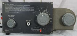
The General Radio 1750-A Sweep Drive was introduced in Catalog O (1956) and remained available through Catalog T (1968).
The Type 1750-A sweep drive is designed to mechanically sweep an oscillator through a flexible universal coupling. The sweep action is reciprocating motion of the attached oscillator's frequency control.
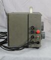
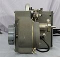
Front-panel controls are available for sweep arc, sweep speed, and manual rotation. The sweep drive provides two synchronized circuits, a horizontal voltage for oscilloscope deflection, and a blanking circuit which eliminates the return trace. With the mechanical sweep and the auxiliary circuits, an oscilloscope display is possible. For every cycle of the oscillator sweep, a blanking signal and horizontal deflection voltage are created. The blanking signal is produced by a synchronized, cam-operated blanking switch. The synchronized oscilloscope horizontal voltage is produced by the oscilloscope deflection rheostat. A set of limit switches are designed to stop the sweep motor if the limits are exceeded. One limit is fixed, the other is adjustable.
A system comprising the 1750-A sweep drive, an oscillator, and oscilloscope are used to create a spectrum display for the device of interest. The device can be a filter, amplifier, network or radio receiver.
Not all oscillators are compatible with the 1750-A, check the oscillator manual for compatibility.
Specifications
- Reciprocating Output Shaft
- Center Position: adjustable within 9 turns
- Sweep Arc: adjustable from 30 to 300°C
- Torque: rated max 24 ounce-inches
- Sweep Speed: Adjustable 0.5 to 5 Hz. (Moment of inertia of load limits maxsafe speed.)
- Flexible Coupling
- Length: 5-¾ inches
- Coupling Limits: shaft diameters ¼ and ⅜ inch; knobs and dials from 1 to 4 inches
- Limit Switch: one limit fixed, the other adjustable within 9 turns
- Sweep Voltage: 2.5 V peak to peak, ungrounded
- Blanking: shorting contact closed during clockwise rotation of driven shaft; ungrounded
Links
Photos
-
-
-
-
-
-
-
-
-
-
-
-
-
-
Oscilloscope Horizontal Rheostat
-
Blanking Switch and Cam
-
Sweep Limit Switch Housing


