1750-A: Difference between revisions
(Created page with "Type '''1750-A Sweep Drive'''. ==Specifications== ==Links== ==Photos== <gallery> </gallery> Category:Recorders and Dial Drives") |
No edit summary |
||
| (3 intermediate revisions by one other user not shown) | |||
| Line 1: | Line 1: | ||
{{GR Product | |||
|model=1750-A | |||
|codes=STUDY | |||
|class=recorders and dial Drives | |||
|summary=Sweep Drive | |||
|image=GR 1750-A Close-Up.jpg | |||
|caption=General Radio 1750-A Sweep Drive | |||
|series= | |||
|introduced=1956 | |||
|discontinued=1968 | |||
|designers= | |||
|manuals= | |||
* [[Media:GR 1750A Sweep Drive 1750-0100-C 05_1961.pdf|General Radio 1750-A Sweep Drive Manual 1750-0100-C 1961]] | |||
{{Catalog History}} | |||
}} | |||
The {{Title|General Radio 1750-A Sweep Drive}} was introduced in {{Catalog O}} and remained available through {{Catalog T}}. | |||
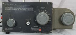
The Type 1750-A sweep drive is designed to mechanically sweep an oscillator through a flexible universal coupling. The sweep action is reciprocating motion of the attached oscillator's frequency control. | |||
Front-panel controls are available for sweep arc, sweep speed, and manual rotation. | |||
The sweep drive provides two synchronized circuits, a horizontal voltage for oscilloscope deflection, and a blanking circuit which eliminates the return trace. | |||
With the mechanical sweep and the auxiliary circuits, an oscilloscope display is possible. | |||
For every cycle of the oscillator sweep, a blanking signal and horizontal deflection voltage are created. | |||
The blanking signal is produced by a synchronized, cam-operated blanking switch. | |||
The synchronized oscilloscope horizontal voltage is produced by the oscilloscope deflection rheostat. | |||
A set of limit switches are designed to stop the sweep motor if the limits are exceeded. One limit is fixed, the other is adjustable. | |||
A system comprising the 1750-A sweep drive, an oscillator, and oscilloscope are used to create a spectrum display for the device of interest. The device can be a filter, amplifier, network or radio receiver. | |||
Not all oscillators are compatible with the 1750-A, check the oscillator manual for compatibility. | |||
==Specifications== | ==Specifications== | ||
* '''Reciprocating Output Shaft''' | |||
* '''Center Position:''' adjustable within 9 turns | |||
* '''Sweep Arc:''' adjustable from 30 to 300°C | |||
* '''Torque:''' rated max 24 ounce-inches | |||
* '''Sweep Speed:''' Adjustable 0.5 to 5 Hz. (Moment of inertia of load limits maxsafe speed.) | |||
* '''Flexible Coupling''' | |||
* '''Length:''' 5-¾ inches | |||
* '''Coupling Limits:''' shaft diameters ¼ and ⅜ inch; knobs and dials from 1 to 4 inches | |||
* '''Limit Switch:''' one limit fixed, the other adjustable within 9 turns | |||
* '''Sweep Voltage:''' 2.5 V peak to peak, ungrounded | |||
* '''Blanking:''' shorting contact closed during clockwise rotation of driven shaft; ungrounded | |||
==Links== | ==Links== | ||
* [[Media:GR Exp 1750-A 04_1955.pdf|Experimenter April 1955 describing Type 1750-A]] | |||
==Photos== | ==Photos== | ||
<gallery> | <gallery> | ||
GR 1750-A Front.jpg | |||
GR 1750-A Front Open.jpg | |||
GR 1750-A Left Side.jpg | |||
GR 1750-A Right Side.jpg | |||
GR 1750-A Rear.jpg | |||
GR 1750-A Rear Right.jpg | |||
GR 1750-A Rear Open.jpg | |||
GR 1750-A Rear Left Open.jpg | |||
GR 1750-A Coupling Side View.jpg | |||
GR 1750-A Coupling Sweeper Side C.jpg | |||
GR 1750-A Coupling Oscillator Side A.jpg | |||
GR 1750-A Coupling Oscillator Side B.jpg | |||
GR 1750-A Coupling Oscillator Side C.jpg | |||
GR 1750-A Oscilloscope Horizontal Rheostat.jpg|Oscilloscope Horizontal Rheostat | |||
GR 1750-A Blanking Switch and Cam.jpg|Blanking Switch and Cam | |||
GR 1750-A Sweep Limit Switch Housing.jpg|Sweep Limit Switch Housing | |||
</gallery> | </gallery> | ||
[[Category:Recorders and Dial Drives]] | [[Category:Recorders and Dial Drives]] | ||
Latest revision as of 05:23, 21 May 2024
The General Radio 1750-A Sweep Drive was introduced in Catalog O (1956) and remained available through Catalog T (1968).
The Type 1750-A sweep drive is designed to mechanically sweep an oscillator through a flexible universal coupling. The sweep action is reciprocating motion of the attached oscillator's frequency control.
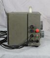
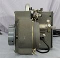
Front-panel controls are available for sweep arc, sweep speed, and manual rotation. The sweep drive provides two synchronized circuits, a horizontal voltage for oscilloscope deflection, and a blanking circuit which eliminates the return trace. With the mechanical sweep and the auxiliary circuits, an oscilloscope display is possible. For every cycle of the oscillator sweep, a blanking signal and horizontal deflection voltage are created. The blanking signal is produced by a synchronized, cam-operated blanking switch. The synchronized oscilloscope horizontal voltage is produced by the oscilloscope deflection rheostat. A set of limit switches are designed to stop the sweep motor if the limits are exceeded. One limit is fixed, the other is adjustable.
A system comprising the 1750-A sweep drive, an oscillator, and oscilloscope are used to create a spectrum display for the device of interest. The device can be a filter, amplifier, network or radio receiver.
Not all oscillators are compatible with the 1750-A, check the oscillator manual for compatibility.
Specifications
- Reciprocating Output Shaft
- Center Position: adjustable within 9 turns
- Sweep Arc: adjustable from 30 to 300°C
- Torque: rated max 24 ounce-inches
- Sweep Speed: Adjustable 0.5 to 5 Hz. (Moment of inertia of load limits maxsafe speed.)
- Flexible Coupling
- Length: 5-¾ inches
- Coupling Limits: shaft diameters ¼ and ⅜ inch; knobs and dials from 1 to 4 inches
- Limit Switch: one limit fixed, the other adjustable within 9 turns
- Sweep Voltage: 2.5 V peak to peak, ungrounded
- Blanking: shorting contact closed during clockwise rotation of driven shaft; ungrounded
Links
Photos
-
-
-
-
-
-
-
-
-
-
-
-
-
-
Oscilloscope Horizontal Rheostat
-
Blanking Switch and Cam
-
Sweep Limit Switch Housing


