1220-A: Difference between revisions
No edit summary |
No edit summary |
||
| (7 intermediate revisions by 2 users not shown) | |||
| Line 1: | Line 1: | ||
{{GR Product | {{GR Product | ||
|model=1220-A | |model=1220-A | ||
|codes=KANOT | |||
|class=oscillators | |class=oscillators | ||
|summary= | |summary=Unit klystron oscillator | ||
|image=GR 1220-A Front Close-up.jpg | |image=GR 1220-A Front Close-up.jpg | ||
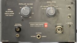
|caption=General Radio 1220-A Unit Klystron Oscillator | |caption=General Radio 1220-A Unit Klystron Oscillator | ||
|series= | |series=1220 | ||
|introduced=1956 | |introduced=1956 | ||
|discontinued=1965 | |discontinued=1965 | ||
| Line 11: | Line 12: | ||
|manuals= | |manuals= | ||
* [[Media:GRwiki 1220-A Klystron Oscillator 932-B 1959.pdf|General Radio 1220-A Klystron Oscillator Manual 932-B 1959]] | * [[Media:GRwiki 1220-A Klystron Oscillator 932-B 1959.pdf|General Radio 1220-A Klystron Oscillator Manual 932-B 1959]] | ||
{{Catalog History}} | |||
}} | }} | ||
The | The {{Title|General Radio 1220-A Unit Klystron Oscillator}} was introduced in {{Catalog O}} and remained available through {{Catalog S}}. | ||
The Type 1220-A is the foundation of for the Unit Klystron Oscillator series and supplied without a Klystron. It contains all fixtures to adapt the various Klystron tubes. | |||
All that is required to change the frequency range is the appropriate Klystron tube. | |||
An internal 1 kHz oscillator followed by a Schmitt trigger provides internal square-wave modulation. | |||
The 1220-A requires an external power supply, the [[1201-B]] is recommended. | |||
The external supply can't supply all the voltages required by the Klystron, so an internal supply is needed which takes 6.3 V<sub>AC</sub> from the [[1201-B]] to develop the regulated Repeller voltage and an unregulated voltage for the Schmitt trigger circuit. | |||
The front panel accepts external modulation selected by the modulation switch as required. | The front panel accepts external modulation selected by the modulation switch as required. | ||
==Specifications== | ==Specifications== | ||
* '''Frequency Range:''' Depends upon klystron tube used (refer to table below) | * '''Frequency Range:''' Depends upon klystron tube used (refer to table below) | ||
* '''Modulation Internal:''' Internal 1 kHz square wave, adjustable within +15 Hz | * '''Modulation Internal:''' Internal 1 kHz square wave, adjustable within +15 Hz | ||
* '''Modulation External:''' External square wave, 50 Hz to 200 kHz; sine or square-wave modulating signal of at least | * '''Modulation External:''' External square wave, 50 Hz to 200 kHz; sine or square-wave modulating signal of at least 15 V<sub>RMS</sub> required | ||
* '''Modulation FM:''' at least 15 MHz excursion obtainable with less than 3 dB change in output; at 60 Hz, | * '''Modulation FM:''' at least 15 MHz excursion obtainable with less than 3 dB change in output; at 60 Hz, an RMS input of about 10 V is suitable. | ||
{| class="wikitable" style="margin:auto" | {| class="wikitable" style="margin:auto" | ||
|+ Klystron Oscillator Data | |+ Klystron Oscillator Data | ||
|- | |- | ||
!Type !! Frequency Range !! Tube !! Output mW | !Type !! Frequency Range !! Tube !! Output [mW] | ||
|- | |- | ||
| [[1220-A1]] || 2700-2960 MHz || 726-C || 100 | | [[1220-A1]] || 2700-2960 MHz || 726-C || 100 | ||
| Line 41: | Line 49: | ||
| [[1220-A6]] || 5100-5900 MHz || 6115 || 80 | | [[1220-A6]] || 5100-5900 MHz || 6115 || 80 | ||
|- | |- | ||
| [[1220-A7]] || 5925-6450 MHz || QK404 | | [[1220-A7]] || 5925-6450 MHz || QK404 || 100 | ||
|- | |- | ||
| [[1220-A8]] || 6200-7425 MHz || 5976 || 90 | | [[1220-A8]] || 6200-7425 MHz || 5976 || 90 | ||
| Line 48: | Line 56: | ||
==Links== | ==Links== | ||
* [[Media:GR Exp 1220-A 03_1956.pdf|Experimenter describing Type 1220-A | * [[Media:GR Exp 1220-A 03_1956.pdf|Experimenter March 1956 describing Type 1220-A]] | ||
==Photos== | ==Photos== | ||
Latest revision as of 23:04, 30 April 2024
The General Radio 1220-A Unit Klystron Oscillator was introduced in Catalog O (1956) and remained available through Catalog S (1965).
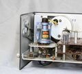
The Type 1220-A is the foundation of for the Unit Klystron Oscillator series and supplied without a Klystron. It contains all fixtures to adapt the various Klystron tubes. All that is required to change the frequency range is the appropriate Klystron tube. An internal 1 kHz oscillator followed by a Schmitt trigger provides internal square-wave modulation.
The 1220-A requires an external power supply, the 1201-B is recommended. The external supply can't supply all the voltages required by the Klystron, so an internal supply is needed which takes 6.3 VAC from the 1201-B to develop the regulated Repeller voltage and an unregulated voltage for the Schmitt trigger circuit.
The front panel accepts external modulation selected by the modulation switch as required.
Specifications
- Frequency Range: Depends upon klystron tube used (refer to table below)
- Modulation Internal: Internal 1 kHz square wave, adjustable within +15 Hz
- Modulation External: External square wave, 50 Hz to 200 kHz; sine or square-wave modulating signal of at least 15 VRMS required
- Modulation FM: at least 15 MHz excursion obtainable with less than 3 dB change in output; at 60 Hz, an RMS input of about 10 V is suitable.
| Type | Frequency Range | Tube | Output [mW] |
|---|---|---|---|
| 1220-A1 | 2700-2960 MHz | 726-C | 100 |
| 1220-A2 | 2950-3275 MHz | 6043 | 90 |
| 1220-A3 | 3400-3960 MHz | 2K29 | 90 |
| 1220-A4 | 3840-4460 MHz | 2K56 | 75 |
| 1220-A5 | 4240-4910 MHz | 2K22 | 100 |
| 1220-A6 | 5100-5900 MHz | 6115 | 80 |
| 1220-A7 | 5925-6450 MHz | QK404 | 100 |
| 1220-A8 | 6200-7425 MHz | 5976 | 90 |


