1864: Difference between revisions
Jump to navigation
Jump to search
No edit summary |
No edit summary |
||
| (2 intermediate revisions by the same user not shown) | |||
| Line 8: | Line 8: | ||
|series= | |series= | ||
|introduced=1970 | |introduced=1970 | ||
|discontinued= | |discontinued=the present day | ||
|designers= | |designers= | ||
|manuals= | |manuals= | ||
* [[Media:GR 1863 and 1864 Instruction Manual 1863-0100-00.pdf|GR 1863 and 1864 Instruction Manual (1863-0100-00)]] | * [[Media:GR 1863 and 1864 Instruction Manual 1863-0100-00.pdf|GR 1863 and 1864 Instruction Manual (1863-0100-00)]] | ||
* [[Media:GR 1863 and 1864 Instruction Manual 1863-0100-B 1973-03.pdf|GR 1863 and 1864 Instruction Manual (1863-0100-B, 1973)]] | |||
* [[Media:GR 1863 and 1864 Instruction Manual 1863-0100-C 1974-08.pdf|GR 1863 and 1864 Instruction Manual (1863-0100-C, 1974)]] (readable schematics) | * [[Media:GR 1863 and 1864 Instruction Manual 1863-0100-C 1974-08.pdf|GR 1863 and 1864 Instruction Manual (1863-0100-C, 1974)]] (readable schematics) | ||
* [https://www.ietlabs.com/pdf/Manuals/1863-64_im.pdf GR1863/1864 Instruction Manual, Aug 2018] @ IET Labs | * [https://www.ietlabs.com/pdf/Manuals/1863-64_im.pdf GR1863/1864 Instruction Manual, Aug 2018] @ IET Labs | ||
* [[Media:GR-1863 and GR-1864 stitched schematics.pdf|GR-1863 and GR-1864 stitched schematics]] | |||
{{Catalog History}} | {{Catalog History}} | ||
}} | }} | ||
| Line 20: | Line 22: | ||
==Specifications== | ==Specifications== | ||
* '''Test Voltage:''' 10 V to 109 V in 1 V steps, 100 V to 1090 V in 10 V steps; 5 mA limit | * '''Test Voltage:''' 10 V to 109 V in 1 V steps, 100 V to 1090 V in 10 V steps; 5 mA limit | ||
* '''Resistance Range:''' 50 kΩ | * '''Resistance Range:''' 50 kΩ to 200 TΩ in 8 ranges | ||
* '''Power:''' 100-125 or 200-250 V<sub>AC</sub>, 50-400 Hz | |||
==Links== | ==Links== | ||
* The | * The [[1863|Type 1863 Megohmmeter]] is similar but with a 20 TΩ top range, and a choice of only five test voltages (50, 100, 100, 250, or 500 V). | ||
==Internals== | ==Internals== | ||
The 1864 is solid-state except for the test voltage supply pass element, a 6AB4 (EC92) vacuum tube. | The 1864 is solid-state except for the test voltage supply pass element, a [[tekwiki:6AB4|6AB4 (EC92) vacuum tube]]. | ||
Current through the unknown is converted to a voltage using decade reference resistors from 2 kΩ to 2 GΩ | Current through the unknown is converted to a voltage using decade reference resistors from 2 kΩ to 2 GΩ. | ||
A four-stage, FET-input amplifier drives an analog meter. | In the highest range (10 TΩ multiplier), feedback is used to multiply the effective reference resistance by a factor of 10. | ||
A four-stage, FET-input amplifier drives an analog meter that is unusual in that its mechanical zero position is on the right end of the scale. | |||
==Photos== | ==Photos== | ||
Latest revision as of 20:22, 27 August 2024
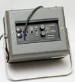
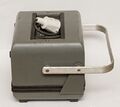
The GR Type 1864 Megohmmeter was introduced in Catalog U (1970). It is still available from IET Labs as of 2024.
Specifications
- Test Voltage: 10 V to 109 V in 1 V steps, 100 V to 1090 V in 10 V steps; 5 mA limit
- Resistance Range: 50 kΩ to 200 TΩ in 8 ranges
- Power: 100-125 or 200-250 VAC, 50-400 Hz
Links
- The Type 1863 Megohmmeter is similar but with a 20 TΩ top range, and a choice of only five test voltages (50, 100, 100, 250, or 500 V).
Internals
The 1864 is solid-state except for the test voltage supply pass element, a 6AB4 (EC92) vacuum tube.
Current through the unknown is converted to a voltage using decade reference resistors from 2 kΩ to 2 GΩ.
In the highest range (10 TΩ multiplier), feedback is used to multiply the effective reference resistance by a factor of 10.
A four-stage, FET-input amplifier drives an analog meter that is unusual in that its mechanical zero position is on the right end of the scale.
Photos
-
-
-
-
-
-
-
-
-
GR-1864 schematic


