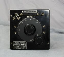
107
The General Radio 107 Series of Variable Inductors were introduced in Catalog A (1916) and certain models remained available through Catalog T (1968).
The Type 107 series was introduced 1916 as "Variometers" or variable inductors of the Ayrton–Perry winding design. The basic design changed little, two circular coils arranged one inside the other. The inner coil is rotated by a calibrated inductance dial. By changing the orientation of the rotor coil, inductance can be varied.
The leads of the two coils are brought out to four binding posts where connections determine series, parallel or mutual inductance settings.
In 1932, five new types − 107-J, 107-K, 107-L, 107-M, and 107-N − were announced. These five types featured a Bakelite panel and walnut case, and were the only types available until production stopped after Catalog T (1968).
The chart below contains published specifications, tags attached to the panel displayed the actual values.
Specifications
| Inductor Type | Serial Self-Inductance | Parallel Self-Inductance | Mutual Inductance | Resistance | Max. Current |
|---|---|---|---|---|---|
| 107-A | 15 to 250 μH | 4 A | |||
| 107-B | 0.25 to 4 mH | 1 A | |||
| 107-C | 8 to 400 μH | 3 A | |||
| 107-D | 0.12 to 6 mH | 1 A | |||
| 107-E | 0.4 to 20 mH | .5 A | |||
| 107-F | 40 to 400 μH | 0.55 Ω | |||
| 107-G | 0.4 to 4 mH | 6.11 Ω | |||
| 107-H | 1.8 to 18 mH | 14.18 Ω | |||
| 107-J | 9 to 50 μH | 2.25 to 12.5 μH | 0 to 10.8 μH | 0.053 Ω | 16 A |
| 107-K | 90 to 500 μH | 22.5 to 125 μH | 0 to 110 μH | 0.38 Ω | 6 A |
| 107-L | 0.9 to 5 mH | 0.225 to 1.25 mH | 0 to 1.1 mH | 5 Ω | 1.7 A |
| 107-M | 9 to 50 mH | 2.25 to 12.5 mH | 0 to 11 mH | 36 Ω | .65 A |
| 107-N | 90 to 500 mH | 22.5 to 125 mH | 0 to 110 mH | 450 Ω | .17 A |
Links
- Experimenter June 1932 describing Type 107 Series
- Experimenter January 1935 describing Type 107 Series
