1114-A
The General Radio 1114-A Frequency Divider was introduced in Catalog Q (1961) and remained available through Catalog S (1965).
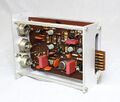
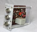
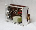
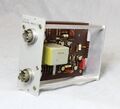
The Type 1114-A Frequency Divider is a component of the Type 1105-A Frequency-Measurement Equipment. Its designed to divide the 5 MHz input signal to produce 1Mhz output. Subsequent modules, 1114-P2 thru 1114-P5 each divide by 10. Optional modules 1114-P6 and 1114-P7 provide 400 Hz and 60 Hz outputs. The output from the modules is essentially a sine wave, although 100 kHz and 10 kHz square wave output is available for the 1114-P2 and 1114-P3 respectivly. The first divider 1114-P1 is a regerative 5:1 divider, 1114-P2 thru 1114-P5 are switching type 10:1 dividers. The plug-in modules are designed to only fit in the correct slot. A switch behind the front cover selects the driving signal from 1 MHz 1114-P1 divider and an external 1 Mhz or 100 kHz inputs.
Specifications
- Input: 5 MHz, 1 MHz, 100 kHz, 50 Ω. 1 V ±50%.
- Output: with 5 MHz input
- Sine Waves: 1 mHz, 100 kHz, 10 kHz, 100 Hz; 400 Hz and 60 Hz optional
- Square Waves: 100 kHz, 10 kHz
- Spurious Signals: better than 34 db down
- Jitter: less than 500 μs for 100 Hz output with respect to 5 MHz input
Links
Photos
GR 1114-P1
GR 1114-P2
GR 1114-P3
GR 1114-P4
GR 1114-P5


