1401: Difference between revisions
Jump to navigation
Jump to search
(→Photos) |
(→Photos) |
||
| Line 43: | Line 43: | ||
==Photos== | ==Photos== | ||
<gallery> | <gallery> | ||
GR 1401-A Front A.jpg | GR 1401-A Front A.jpg | ||
GR 1401-B Front A.jpg | GR 1401-B Front A.jpg | ||
GR 1401-C Front.jpg | GR 1401-C Front.jpg | ||
GR 1401-D Close-Up. | GR 1401-D Close-Up.JPG | ||
</gallery> | </gallery> | ||
[[Category:Capacitance Standards]] | [[Category:Capacitance Standards]] | ||
Revision as of 02:55, 11 May 2024
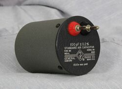
The General Radio 1401 Series Standard Air Capacitors was introduced in Catalog M (1951) and remained available through Catalog S (1965).
The Type 1401 series are two terminal air capacitors designed as laboratory reference or working capacitance standards. They features all aluminum construction with shielded covers. Connections are Type 274 plugs spaced ¾ inches on center. This spacing matches the Type 716-C making them useful as balancing capacitors when performing substitution measurements. The Type 1401 series is comprised of four capacitor types 1401-A, 1401-B, 1401-C, and 1401-D.
Specifications
- Stability: Capacitance change is less than 0.05% per year
- Residual Impedances: The series inductance of all units is approximately 0.05 μH
- Temperature Coefficient of Capacitance: Typically 10 to 20 ppm/C° between 20° and 70°C.
- Terminals: Type 274 plugs, spaced ¾ inch on centers, to plug into Type 938 binding posts
Links
| Type | Insertion Capacitance | Initial Accuracy | Peak Volts | Dissipation Factor | Catalog Number |
|---|---|---|---|---|---|
| 1401-A | 100 pF | 0.2% | 1500 V | 0.0001 | 1401-9701 |
| 1401-B | 200 pF | 0.15% | 1200 V | 0.00005 | 1401-9702 |
| 1401-C | 500 pF | 0.12% | 900 V | 0.00002 | 1401-9703 |
| 1401-D | 1000 pF | 0.1% | 700 V | 0.00001 | 1401-9704 |


