1607-A: Difference between revisions
(→Photos) |
(→Photos) |
||
| Line 38: | Line 38: | ||
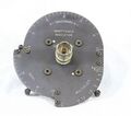
GR 1607-A Immittance Indicator A.jpg|1607-P9 Immittance Indicator | GR 1607-A Immittance Indicator A.jpg|1607-P9 Immittance Indicator | ||
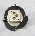
GR 1607-P10 and P11.jpg|1607-P10 & 1607-P11 Multiplier Plates | GR 1607-P10 and P11.jpg|1607-P10 & 1607-P11 Multiplier Plates | ||
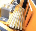
GR 1607-A Case Storage A.jpg | GR 1607-A Case Storage A.jpg|1607-P7-Δ/2 | ||
GR 1607-A Case Storage Bottom B.jpg|1607-P5 & 1607-P6 Range Extension Unit and Support | GR 1607-A Case Storage Bottom B.jpg|1607-P5 & 1607-P6 Range Extension Unit and Support | ||
GR 1607-P3 Variable Capacitor.jpg|1607-P3 Variable Air Capacitor | GR 1607-P3 Variable Capacitor.jpg|1607-P3 Variable Air Capacitor | ||
Revision as of 08:15, 27 April 2024
The General Radio 1607-A Transfer-Function and Immittance Bridge was introduced in Catalog P (1959) and remained available through Catalog U (1970).
Specifications
- Frequency Range: 25 to 1500 MHz, with reduced accuracy above 1000 MHz and when flexible line-extension cables (required below 150 MHz) are used
- Measurement Ranges and Accuracy: See manual
Links
Photos
-
-
1607-3130 Storage Box
-
-
-
-
-
-
-
1607-P9 Immittance Indicator
-
1607-P10 & 1607-P11 Multiplier Plates
-
1607-P7-Δ/2
-
1607-P5 & 1607-P6 Range Extension Unit and Support
-
1607-P3 Variable Air Capacitor
-
1607-P7-Δ 43-cm Air Line & 1607-P1 Adjustable Stub
-
1607-3030 Main Instrument
-
1607-3030 Main Instrument
-
1607-3030 Main Instrument
-
1607-3030 Main Instrument
-
1607-3030 Main Instrument
-
1607-P9 Immittance Indicator
-
1607-P9 Immittance Indicator
-
874-U and 874-U-S2 U-Line Sections
-
-
1607-P7-Δ 43-cm Air Line & 1607-P1 Adjustable Stub
-
1607-P2 Tee & 1607-P4 Termination
-
1607-P2 Tee & 1607-P4 Termination
-
1607-P3 Variable Air Capacitor
-
1607-P5 & 1607-P6 Range Extension Unit and Support
-
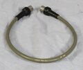
1607-P8-2Δ Patch Cord
-
874-R20A Patch Cord
-
1607-P8-4Δ Patch Cord
-
1607-P8-5Δ Patch Cord
-
1607-P8-6Δ Patch Cord


