874-LBA: Difference between revisions
No edit summary |
No edit summary |
||
| Line 17: | Line 17: | ||
By observing minima and maxima of a standing-wave pattern, parameters like frequency, standing-wave ratio, or impedance can be measured, and thereby the characteristics of a circuit connected to the load side of the line can be determined. Applications include analysis of antennas, components, coaxial elements, and networks. | By observing minima and maxima of a standing-wave pattern, parameters like frequency, standing-wave ratio, or impedance can be measured, and thereby the characteristics of a circuit connected to the load side of the line can be determined. Applications include analysis of antennas, components, coaxial elements, and networks. | ||
The 874-LBA is an update of the [[874-LB]], featuring improved accuracy and carriage construction. The redesigned carriage is controlled by a nylon cord and a series of pulleys to remove its drive control to a fixed position at the load end. | The 874-LBA is an update of the [[874-LB]], featuring improved accuracy and carriage construction. The redesigned carriage is controlled by a nylon cord forming a complete loop, and a series of pulleys to remove its drive control to a fixed position at the load end. This reduces changes in probe coupling caused by changing forces on the carriage. | ||
The 874-LBA was supplied with a protective wooden case, a spare nylon cable, and a crystal detector. | The 874-LBA was supplied with a protective wooden case, a spare nylon cable, and a crystal detector. | ||
| Line 25: | Line 25: | ||
* '''Characteristic Impedance:''' 50 Ω, ±0.5% | * '''Characteristic Impedance:''' 50 Ω, ±0.5% | ||
* '''Scale Accuracy:''' ±(0.1 mm +0.05%) | * '''Scale Accuracy:''' ±(0.1 mm +0.05%) | ||
* '''Frequency Range:''' 300 MHz to 5 GHz | * '''Frequency Range:''' 300 (150) MHz to 5 GHz | ||
* '''Length:''' 50 cm (λ/2 @ 300 MHz, λ/4 @ 150 MHz) | |||
* '''Constancy of Probe Penetration:''' ±1½% | * '''Constancy of Probe Penetration:''' ±1½% | ||
* '''Residual SWR:''' 1.025 @ 1 GHz, 1.07 @ 4 GHz | |||
==Links== | ==Links== | ||
Revision as of 01:12, 26 April 2024
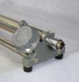
The General Radio 874-LBA Slotted Line was introduced in Catalog O (1956) and remained available through Catalog S (1965). Its function is to observe the electric field along the inside of a coaxial transmission line using a carriage-mounted probe moving along the line.
By observing minima and maxima of a standing-wave pattern, parameters like frequency, standing-wave ratio, or impedance can be measured, and thereby the characteristics of a circuit connected to the load side of the line can be determined. Applications include analysis of antennas, components, coaxial elements, and networks.
The 874-LBA is an update of the 874-LB, featuring improved accuracy and carriage construction. The redesigned carriage is controlled by a nylon cord forming a complete loop, and a series of pulleys to remove its drive control to a fixed position at the load end. This reduces changes in probe coupling caused by changing forces on the carriage.
The 874-LBA was supplied with a protective wooden case, a spare nylon cable, and a crystal detector.
Specifications
- Characteristic Impedance: 50 Ω, ±0.5%
- Scale Accuracy: ±(0.1 mm +0.05%)
- Frequency Range: 300 (150) MHz to 5 GHz
- Length: 50 cm (λ/2 @ 300 MHz, λ/4 @ 150 MHz)
- Constancy of Probe Penetration: ±1½%
- Residual SWR: 1.025 @ 1 GHz, 1.07 @ 4 GHz
Links
- Experimenter December 1954 describing Type 874-LBA
- 1N23B Microwave Diode Data
- AT&T Archives Wave Machine Tutorial @ YouTube


