716-CS1: Difference between revisions
Jump to navigation
Jump to search
No edit summary |
No edit summary |
||
| Line 3: | Line 3: | ||
|codes=BOGEY, BACON | |codes=BOGEY, BACON | ||
|class=impedance measurement | |class=impedance measurement | ||
|summary= | |summary=Capacitance bridge | ||
|image=GR 716-CSI Front Close-up.jpg | |image=GR 716-CSI Front Close-up.jpg | ||
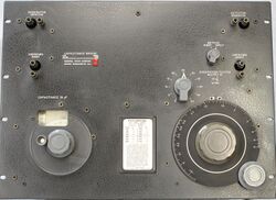
|caption=General Radio 716-CS1 Capacitance Bridge | |caption=General Radio 716-CS1 Capacitance Bridge | ||
Revision as of 18:50, 16 April 2024
The General Radio 716-CS1 Capacitance Bridge was introduced in Catalog N (1954) and remained available through Catalog S (1965).
The Type 716-CS1 is a direct-reading capacitance bridge operating at a frequency of 1 MHz. It differs from the 716-C using the 722-N variable capacitor and input transformer both designed to operate at 1 MHz. The 716-CS1 requires a generator and detector operating at 1 MHz, the 1214-M oscillator and 1212-A - 1212-P2 detector-filter combination are recommended. For more information and specifications see the 716-C.
Specifications
- Capacitance Range: Direct method, 100 to 1100 pF; Substitution method, 0.1 to 1000 pF
- Dissipation Factor Range: Direct method, 0.00002 to 0.056; Substitution method, see manual
- Frequency: Direct reading at 1 MHz; 0.5 to 3 MHz with correction
- Other Specifications: See Type 716-C
Links
- Experimenter describing Type 716-CS1 February 1952
- Experimenter describing Type 716-A December 1936
- Experimenter describing Type 716-B April 1942
- Experimenter describing Type 716-C April 1947


