544-B: Difference between revisions
Jump to navigation
Jump to search
No edit summary |
No edit summary |
||
| Line 25: | Line 25: | ||
* [[Media:GRwiki_Catalog_Q_OCR_1961.pdf |Q (1961)]], p.8 | * [[Media:GRwiki_Catalog_Q_OCR_1961.pdf |Q (1961)]], p.8 | ||
* [[Media:GRwiki_Catalog_R_OCR_1963.pdf |R (1963)]], p.47 | * [[Media:GRwiki_Catalog_R_OCR_1963.pdf |R (1963)]], p.47 | ||
{{RefDisplayStart}} | |||
{{References}} | |||
{{RefDisplayEnd}} | |||
}} | }} | ||
The '''General Radio 544-B Megohm Bridge''' was introduced in {{Catalog K1}} and remained available through {{Catalog R}}. | The '''General Radio 544-B Megohm Bridge''' was introduced in {{Catalog K1}} and remained available through {{Catalog R}}. | ||
| Line 59: | Line 62: | ||
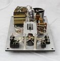
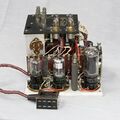
GR 544-B Case Inside.jpg | GR 544-B Case Inside.jpg | ||
</gallery> | </gallery> | ||
[[Category:Impedance measurement]] | [[Category:Impedance measurement]] | ||
Revision as of 09:11, 3 April 2024
The General Radio 544-B Megohm Bridge was introduced in Catalog K1 (1939) and remained available through Catalog R (1963).
The Type 544-B Megohm Bridge is a null instrument using a Wheatstone bridge circuit. It uses a built-in vacuum tube voltmeter (VTVM) as a detector, and an AC power supply 544-P3 for both VTVM and the Unknown voltages.
The 544-B comes installed in an oak hardwood case with operating instructions attached to the inside of its cover. A flexible jack with lead is mounted in the cover for checking the internal standards as explained in the manual. The 544-B was also available modified for use with a battery power supply.
Specifications
- Range: 0.1 MΩ to 1,000,000 MΩ
- Accuracy: ±3% on the 0.1, 1, and 10 multipliers; ±4% on the 100 and 1000 multipliers
- Output Voltage AC Supply: 100 V or 500 V, jumper-selectable
- Short Circuit Current AC Supply: 12 mA
Links
- Experimenter describing Type 544-B July 1937
- Experimenter describing Type 544-B June 1939
- Experimenter describing Type 544-B February 1940


