1021-P2: Difference between revisions
Jump to navigation
Jump to search
No edit summary |
No edit summary |
||
| Line 19: | Line 19: | ||
* '''Frequency Calibration:''' Direct reading to ±1%. | * '''Frequency Calibration:''' Direct reading to ±1%. | ||
* '''Output Voltage:''' Continuously adjustable from 0.5 μV to 1.0 V, open-circuit. | * '''Output Voltage:''' Continuously adjustable from 0.5 μV to 1.0 V, open-circuit. | ||
* '''Output Impedance:''' 50 | * '''Output Impedance:''' 50 Ω ±10%. | ||
==Links== | ==Links== | ||
Revision as of 13:49, 29 February 2024
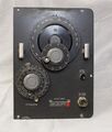
The General Radio 1021-P2 UHF Unit is part of Type 1021-A series of Standard Signal Generators introduced in 1951 and available in Catalog N and remained available through Catalog S 1965. Type 1021-A models equipped with 1021-P2 were given the designation Type 1021-AU.
Specifications
- Carrier Frequency Range: 250 MHz to 920 MHz in one band.
- Frequency Calibration: Direct reading to ±1%.
- Output Voltage: Continuously adjustable from 0.5 μV to 1.0 V, open-circuit.
- Output Impedance: 50 Ω ±10%.
Links
- Experimenter describing Type 1021-A 1950
- Experimenter describing Type 1021-A and Type 1021-P3A 1955
- Experimenter describing Type 1021-P10 1957
Photos
-
-
-
-
GR 874-VR Voltmeter Rectifier
-
-
Oscillator Section
-
Attenuator - Oscillator Tuning Section
-


