107-K: Difference between revisions
Jump to navigation
Jump to search
No edit summary |
|||
| Line 25: | Line 25: | ||
* '''Maximum Current:''' 6 A | * '''Maximum Current:''' 6 A | ||
* '''DC Resistance:''' 0.38 Ω | * '''DC Resistance:''' 0.38 Ω | ||
* '''Maximum Power:''' 15W | |||
==Links== | ==Links== | ||
Revision as of 20:02, 3 May 2024
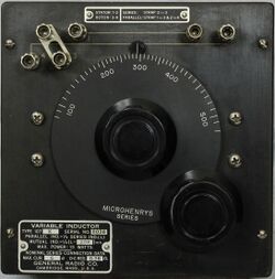
The General Radio 107-K Variable Inductor was introduced in Catalog H (1935) and remained available through Catalog T (1968).
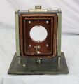
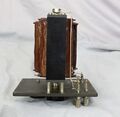
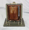
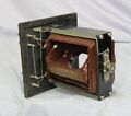
The Type 107-K is variable inductor or "Variometer" of the Ayrton–Perry winding design. It contains two circular coils arranged one inside the other, a stator or fixed coil and a rotor coil attached to a calibrated inductance dial. By changing the orientation of the rotor coil inductance varied. The leads of the two coils are brought out to four binding posts where connections determine series, parallel or mutual inductance settings. Shorting links are provided for this purpose. The 107-K featured a Bakelite panel and walnut case. A tag attached to the panel displays the actual values.
Specifications
- Self-Inductance Series: 90 to 500 μH
- Self-Inductance Parallel: 22.5 to 125 μH
- Mutual-Inductance: 0 to 110 μH
- Accuracy: 1%
- Maximum Current: 6 A
- DC Resistance: 0.38 Ω
- Maximum Power: 15W
Links
- Experimenter June 1932 describing Type 107 Series
- Experimenter January 1935 describing Type 107 Series
