1606-A: Difference between revisions
Jump to navigation
Jump to search
No edit summary |
No edit summary |
||
| Line 2: | Line 2: | ||
|model=1606-A | |model=1606-A | ||
|class=impedance measurement | |class=impedance measurement | ||
|summary= | |summary=RF Bridge | ||
|image=GR 1206-A Close-up.jpg | |image=GR 1206-A Close-up.jpg | ||
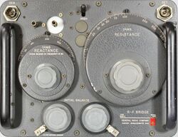
|caption=General Radio 1606-A RF Bridge | |caption=General Radio 1606-A RF Bridge | ||
Revision as of 02:27, 18 April 2024
The General Radio 1606-A RF Bridge was introduced in Catalog O (1956) and remained available through Catalog S (1965).
The Type 1606-A is null type instrument for measuring relatively low impedances. It's frequency range is 400 kHz to 60 MHz but can be expanded with reduced accuracy. Any oscillator delivering .1 to 10 V at the frequency of interest can be used as a generator. The detector often used is a radio receiver of the proper frequency with adjustable gain and AVC. The recommended detectors are of the heterodyne or DNT type. Applications for 1606-A antennas, components and networks of relatively low impedance.
Specifications
- Frequency Range: 400 kHz to 60 MHz
- Reactance Range ±5000 ohms at 1 MHz, range varies inversely with frequency, See manual
- Resistance Range: 0 to 1000 Ω


