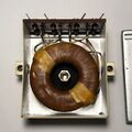
941-A: Difference between revisions
Jump to navigation
Jump to search
(Created page with "Type '''941-A Toroidal Transformer'''. ==Specifications== ==Links== ==Photos== <gallery> </gallery> Category:Parts and Accessories") |
No edit summary |
||
| Line 1: | Line 1: | ||
{{GR Product | |||
|model=941-A | |||
|codes=TRANTORCAT,0941-9701 | |||
|class=parts and accessories | |||
|summary=Toroidal Transformer | |||
|image=GR 971 Close-Up.jpg | |||
|caption=General Radio 941-A Toroidal Transformer | |||
|series= | |||
|introduced=1951 | |||
|discontinued=1965 | |||
|designers= | |||
|manuals= | |||
* '''Manual Needed.''' | |||
{{Catalog History}} | |||
}} | |||
The {{Title|General Radio 941-A Toroidal Transformer}} was introduced in {{Catalog M}} and remained available through {{Catalog S}}. | |||
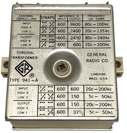
The Type 941-A is toroidal wound matching transformer operating at audio to ultrasonic frequencies. This transformer is designed for use as an impedance-matching and bridging transformer in low-level 600 Ω communication circuits. | |||
The table below summarizes the specifications and connections for the desired output impedance and frequency response. | |||
==Specifications== | ==Specifications== | ||
* '''Primary Impedance:''' 600 Ω | |||
* '''Zero Signal Inductance:''' inner windings, in series, at least 5 henry; outer windings, in series, at least 20 henry | |||
* '''Resistance:''' inner windings in series, 9 Ω; outer windings in series 34 Ω (approximately) | |||
* '''Distortion:''' varies with power; <1% at 1.26 W, <.5% at 1 W, <.2% at .5 W, <.1% at 3m mW | |||
{| class="wikitable" style="margin:auto" | |||
|+ Type 941-A Frequency and Impedance Ranges | |||
|- | |||
! Output<br>Impedance !! Frequency<br>for 1 DB Drop!!Flat Insertion<br>Loss less than!!Input<br>Connections!!Output<br>Connections | |||
|- | |||
| 9600 Ω || 80 Hz - 100 kHz || 0.3 dB || H4 & L1 || H8 & L5 | |||
|- | |||
| 2400 Ω || 20 Hz - 135 kHz || 0.2 dB || H4 & L1 || H8 & L5 | |||
|- | |||
| 2400 Ω || 80 Hz - 340 kHz || 0.2 dB || H4 & L1 || H8 & L5 | |||
|- | |||
| 600 Ω || 20 Hz - 200 kHz || 0.1 dB || H4 & L1 || H8 & L5 | |||
|- | |||
| 600 Ω || 20 Hz - 200 kHz || 0.3 dB || H8 & L5 || H4 & L1 | |||
|- | |||
| 150 Ω || 5 Hz - 50 kHz || 0.3 dB || H8 & L5 || H4 & L1 | |||
|- | |||
| 150 Ω || 20 Hz - 200 kHz || 0.3 dB || H8 & L5 || H4 & L1 | |||
|- | |||
| 37.5 Ω || 5 Hz - 50 kHz || 0.3 dB || H8 & L5 || H4 & L1 | |||
|- | |||
|} | |||
* '''H = High and L = Low for connection phasing''' | |||
==Links== | ==Links== | ||
* [[Media:GR Exp 941-A 09_1950.pdf|Experimenter September 1950 describing Type 941-A]] | |||
==Photos== | ==Photos== | ||
<gallery> | <gallery> | ||
GR 941 Front A.jpg | |||
GR 941 Left Side A.jpg | |||
GR 941 Right Side A.jpg | |||
GR 941 Terminal View A.jpg | |||
GR 941 Back Side.jpg | |||
GR 941 Inside.jpg | |||
GR 941 Inside A.jpg | |||
</gallery> | </gallery> | ||
[[Category:Parts and Accessories]] | [[Category:Parts and Accessories]] | ||
Latest revision as of 09:54, 13 July 2024
The General Radio 941-A Toroidal Transformer was introduced in Catalog M (1951) and remained available through Catalog S (1965).
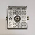
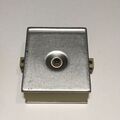
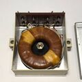
The Type 941-A is toroidal wound matching transformer operating at audio to ultrasonic frequencies. This transformer is designed for use as an impedance-matching and bridging transformer in low-level 600 Ω communication circuits.
The table below summarizes the specifications and connections for the desired output impedance and frequency response.
Specifications
- Primary Impedance: 600 Ω
- Zero Signal Inductance: inner windings, in series, at least 5 henry; outer windings, in series, at least 20 henry
- Resistance: inner windings in series, 9 Ω; outer windings in series 34 Ω (approximately)
- Distortion: varies with power; <1% at 1.26 W, <.5% at 1 W, <.2% at .5 W, <.1% at 3m mW
| Output Impedance |
Frequency for 1 DB Drop |
Flat Insertion Loss less than |
Input Connections |
Output Connections |
|---|---|---|---|---|
| 9600 Ω | 80 Hz - 100 kHz | 0.3 dB | H4 & L1 | H8 & L5 |
| 2400 Ω | 20 Hz - 135 kHz | 0.2 dB | H4 & L1 | H8 & L5 |
| 2400 Ω | 80 Hz - 340 kHz | 0.2 dB | H4 & L1 | H8 & L5 |
| 600 Ω | 20 Hz - 200 kHz | 0.1 dB | H4 & L1 | H8 & L5 |
| 600 Ω | 20 Hz - 200 kHz | 0.3 dB | H8 & L5 | H4 & L1 |
| 150 Ω | 5 Hz - 50 kHz | 0.3 dB | H8 & L5 | H4 & L1 |
| 150 Ω | 20 Hz - 200 kHz | 0.3 dB | H8 & L5 | H4 & L1 |
| 37.5 Ω | 5 Hz - 50 kHz | 0.3 dB | H8 & L5 | H4 & L1 |
- H = High and L = Low for connection phasing
