1140-A: Difference between revisions
Jump to navigation
Jump to search
(Created page with "Type '''1140-A UHF Wavemeter'''. ==Specifications== ==Links== ==Photos== <gallery> </gallery> Category:Frequency Standards and Meters") |
No edit summary |
||
| Line 1: | Line 1: | ||
{{GR Product | |||
|model=1140-A | |||
|class=frequency standards and meters" | |||
|summary=UHF Wavemeter | |||
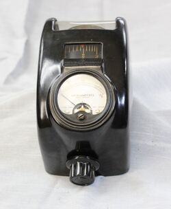
|image=GR 1140-A Front.jpg | |||
|caption=General Radio 1140-A UHF Wavemeter | |||
|series= | |||
|introduced=1948 | |||
|discontinued=1954 | |||
|designers= | |||
|manuals= | |||
}} | |||
The '''General Radio 1140-A UHF Wavemeter''' introduced in 1948 Catalog L and remained available through Catalog N 1954. | |||
The 1140-A is a simple device to measure frequency in the UHF range of 240 to 1200 MHz with 2% accuracy. Behind the rear window is what's | |||
called a Butterfly circuit which varies capacitance and inductance simultaneously to atain resonance. Resonance is indicated with a | |||
micro ammeter. | |||
==Specifications== | ==Specifications== | ||
* '''Frequency Range:''' 240-1200 Mc in one range. | |||
* '''Accuracy:''' ±2% of the indicated frequency. | |||
* '''Detector:''' A type 1N22 Crystal Detector (Microwave Diode). | |||
==Links== | ==Links== | ||
* [[Media:GRwiki Exp 1140-A 10_1945.pdf|Experimenter describing Type 1140-A October 1945]] | |||
==Photos== | ==Photos== | ||
<gallery> | <gallery> | ||
GR 1140-A Front.jpg | |||
GR 1140-A Inside Front.jpg | |||
GR 1140-A Inside Left.jpg | |||
GR 1140-A Inside Rear Butterfly B.jpg | |||
GR 1140-A Inside Rear Butterfly.jpg | |||
GR 1140-A Inside Rear.jpg | |||
GR 1140-A Inside Right.jpg | |||
</gallery> | </gallery> | ||
[[Category: | [[Category:frequency standards and meters]] | ||
Revision as of 08:26, 2 March 2024
The General Radio 1140-A UHF Wavemeter introduced in 1948 Catalog L and remained available through Catalog N 1954. The 1140-A is a simple device to measure frequency in the UHF range of 240 to 1200 MHz with 2% accuracy. Behind the rear window is what's called a Butterfly circuit which varies capacitance and inductance simultaneously to atain resonance. Resonance is indicated with a micro ammeter.
Specifications
- Frequency Range: 240-1200 Mc in one range.
- Accuracy: ±2% of the indicated frequency.
- Detector: A type 1N22 Crystal Detector (Microwave Diode).


