1001-A: Difference between revisions
Jump to navigation
Jump to search
No edit summary |
No edit summary |
||
| Line 1: | Line 1: | ||
[[File:GR 1001-A Front A.jpg|thumb|450px|right|General Radio 1001-A Standard Signal Generator]] | [[File:GR 1001-A Front A.jpg|thumb|450px|right|General Radio 1001-A Standard Signal Generator]] | ||
The '''General Radio 1001-A''' is a standard signal generator [[introduced in 1951]] Catalog M and available | The '''General Radio 1001-A''' is a standard signal generator [[introduced in 1951]] Catalog M and remained available through Catalog73. | ||
The 1001-A is a lab grade signal generator covering a frequency range 0f 5 kHz to 50 MHz. It has a calibrated attenuator with output 0.1 μV to 200 Mv | The 1001-A is a lab grade signal generator covering a frequency range 0f 5 kHz to 50 MHz. It has a calibrated attenuator with output 0.1 μV to 200 Mv | ||
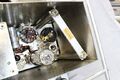
also 2 V direct output. The internal RF oscillator and turret band switch are removable for servicing. Inside the cabinet is an alignment tool (¼ hex) for adjusting the oscillator turret. | also 2 V direct output. The internal RF oscillator and turret band switch are removable for servicing. Inside the cabinet is an alignment tool (¼ hex) for adjusting the oscillator turret. | ||
Revision as of 21:14, 21 February 2024

The General Radio 1001-A is a standard signal generator introduced in 1951 Catalog M and remained available through Catalog73. The 1001-A is a lab grade signal generator covering a frequency range 0f 5 kHz to 50 MHz. It has a calibrated attenuator with output 0.1 μV to 200 Mv also 2 V direct output. The internal RF oscillator and turret band switch are removable for servicing. Inside the cabinet is an alignment tool (¼ hex) for adjusting the oscillator turret.
Specifications
- Frequency Range: 5 kHz to 50 MHz in 8 bands.
- Accuracy: ±1% of reading.
- Stability: Warmup drift is in the order of 0.25%. Half the maximum drift is reached in approximitly 1½ hours.
- Amplitude Modulation: 0 to 80%, continuously variable, indicated on the panel meter to ±10% of reading.
- Modulation Frequency: 400 Hz internal, 20 Hz to 15 kHz external modulation.
- Output Impedance: 10 Ω except the 100 mV multiplier setting 50 Ω, 300 Ω at the 2 V output.
Manuals
Links
Photos
-

-

Top Deck
-

Bottom Deck
-

RF Unit (Cover Removed)
-
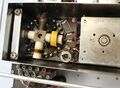
RF Turret Switch
-
Output Amplifier 6L6G
-

Accessory Storage Area
-

Alignment Tool Storage
-

Alignment Tool


