1685: Difference between revisions
(Created page with "Type '''1685 Digital Impedance Meter'''. ==Specifications== ==Links== ==Photos== <gallery> </gallery> Category:Impedance measurement") |
No edit summary |
||
| Line 1: | Line 1: | ||
{{GR Product | |||
|model=1685 | |||
|codes=1685-9702 | |||
|class=impedance measurement | |||
|summary=Digital Impedance Meter | |||
|image=GR 1685 Close-Up.jpg | |||
|caption=General Radio 1685 Digital Impedance Meter | |||
|series=1685 | |||
|introduced=1978 | |||
|discontinued=1978+ | |||
|designers= | |||
|manuals= | |||
* [[Media:GR 1685 Digital Impedance Meter 1685-0150-A 09_1975.pdf|General Radio 1685 Digital Impedance Meter 1685-0150-A 1975]] | |||
{{Catalog History}} | |||
}} | |||
The {{Title|General Radio 1685 Digital Impedance Meter}} was available in {{Catalog 1978}} only. | |||
The Type 1685 is a combination digital and analog impedance measuring device. The CRL values are displayed by a five digit LED display while D and Q use an analog system. Capacitance and inductance are measured at two selectable frequencies, 120 Hz and 1 kHz while resistance is measured using dc voltages. It uses and eight position range switch for capacitance and inductance measurements and a ninth position for high resistance measurements. Above the range switch are illuminated arrows pointing to the range of greatest resolution. The analog DQ dial uses similar illuminated arrows guiding the user towards the null. | |||
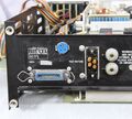
The 1685 has a comparator for Go/No Go testing of components. Limits are set with five decade switches for low and high values and indicator lamps for the results. Also provided is an indicator for high D or low Q if these values exceed the DQ dial setting. The four connections to the unknown are provided a special connector at the rear of the instrument, a test fixture or special cable are required. The Type [[1685-P1]] is the recommended test fixture. | |||
==Specifications== | ==Specifications== | ||
* '''Capacitance Range:''' 0.01 pF to 20,000 μF | |||
* '''Inductance Range:''' 0.01 μH to 2000 H | |||
* '''Resistance:''' 0.1 mΩ to 20 MΩ | |||
* '''Dissipation Factor: 0 to 10 | |||
* '''Q Factor:''' .1 to infinity | |||
* '''Basic Accuracy:''' 0.1% basic accuracy for dc and 1 kHz; 0.5% for 120 Hz measurements | |||
==Links== | ==Links== | ||
==Photos== | |||
<gallery> | <gallery> | ||
GR 1685 Front.jpg | |||
GR 1685 Right Side.jpg | |||
GR 1685 Rear.jpg | |||
GR 1685 Operation.jpg | |||
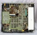
GR 1685 Inside Top.jpg | |||
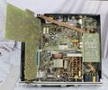
GR 1685 Inside Top Rear Left.jpg | |||
GR 1685 Inside Top Rear Right.jpg | |||
GR 1685 Inside Top Front Left.jpg | |||
GR 1685 Inside Top Front Right.jpg | |||
GR 1685 Inside Top Fold Out.jpg | |||
GR 1685 Inside Top Board A.jpg | |||
GR 1685 Inside Top Board B.jpg | |||
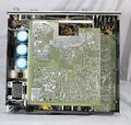
GR 1685 Inside Bottom.jpg | |||
GR 1685 Inside Rear Panel.jpg | |||
GR 1685 Inside Rear Panel Close-Up.jpg | |||
</gallery> | </gallery> | ||
[[Category:Impedance measurement]] | [[Category:Impedance measurement]] | ||
Revision as of 04:31, 6 June 2024
The General Radio 1685 Digital Impedance Meter was available in Catalog 1978 only.
The Type 1685 is a combination digital and analog impedance measuring device. The CRL values are displayed by a five digit LED display while D and Q use an analog system. Capacitance and inductance are measured at two selectable frequencies, 120 Hz and 1 kHz while resistance is measured using dc voltages. It uses and eight position range switch for capacitance and inductance measurements and a ninth position for high resistance measurements. Above the range switch are illuminated arrows pointing to the range of greatest resolution. The analog DQ dial uses similar illuminated arrows guiding the user towards the null.
The 1685 has a comparator for Go/No Go testing of components. Limits are set with five decade switches for low and high values and indicator lamps for the results. Also provided is an indicator for high D or low Q if these values exceed the DQ dial setting. The four connections to the unknown are provided a special connector at the rear of the instrument, a test fixture or special cable are required. The Type 1685-P1 is the recommended test fixture.
Specifications
- Capacitance Range: 0.01 pF to 20,000 μF
- Inductance Range: 0.01 μH to 2000 H
- Resistance: 0.1 mΩ to 20 MΩ
- Dissipation Factor: 0 to 10
- Q Factor: .1 to infinity
- Basic Accuracy: 0.1% basic accuracy for dc and 1 kHz; 0.5% for 120 Hz measurements


