1822: Difference between revisions
Jump to navigation
Jump to search
(Created page with "Type '''1822 Digital Voltmeter Calibrator'''. ==Specifications== ==Links== ==Photos== <gallery> </gallery> Category:Meters") |
No edit summary |
||
| Line 1: | Line 1: | ||
{{GR Product | |||
|model=1822 | |||
|codes=1822-9700 | |||
|class=meters | |||
|summary=Digital Voltmeter Calibrator | |||
|image=GR 1822 Close-Up.jpg | |||
|caption=General Radio 1822 Digital Voltmeter Calibrator | |||
|series= | |||
|introduced=1970 | |||
|discontinued=1970 | |||
|designers= | |||
|manuals= | |||
* '''Manual Needed.''' | |||
{{Catalog History}} | |||
}} | |||
The {{Title|General Radio 1822 Digital Voltmeter Calibrator}} was available in {{Catalog U}} only. | |||
The Type 1822 is designed to produce accurate voltages for the testing and calibration of digital voltmeters. It can be used | |||
as a precise voltage reference from 100 μV dc to 1111.1 V dc for laboratory use. The output voltage can set to any value with five digit resolution, the resolution is adjustable. The output voltage is displayed using a mechanical digital display with automatic units and decimal placement. External programming is available through a rear panel connector along with an internal automatic step function. Other features include an interference voltage function, polarity reversal, and adjustable output impedance. | |||
==Specifications== | ==Specifications== | ||
* '''Output Voltage:''' 100 μV dc to 1111.1 V dc in 7 decade ranges | |||
* '''Output Impedance:''' <0.5 Ω on 1 V through 1 kV ranges; 200 Ω on 1 mV through 100 mV ranges; A l kΩ, 10 kΩ, or 100 kΩ output resistor can be added to above impedances by front-panel selector switch | |||
* '''Output Current: 10 mA at full range on 1, 10, and 100-V ranges; 1 mA on 1 kV range | |||
* '''Accuracy:''' ±(30 ppm of voltage + 10 ppm of full range + 3 μV) on all ranges except ±(50 ppm of voltage + 10 ppm of full range) on 1-kV range; Accuracy of rear-panel voltages ≤111 mV, ±(30 ppm of voltage + 10 ppm of range +0.5 μV) | |||
==Links== | ==Links== | ||
* [[Media:GR Exp 1822 03_1969.pdf|Experimenter March 1969 describing Type 1822]] | |||
==Photos== | ==Photos== | ||
<gallery> | <gallery> | ||
GR 1822 Front.jpg | |||
GR 1822 Side.jpg | |||
GR 1822 Rear.jpg | |||
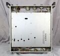
GR 1822 Inside Top.jpg | |||
GR 1822 Inside Top wo Cover.jpg | |||
GR 1822 Inside Top Front Close-Up.jpg | |||
GR 1822 Inside Top Front Left.jpg | |||
GR 1822 Inside Top Front Right.jpg | |||
GR 1822 Inside Top Rear Left.jpg | |||
GR 1822 Inside Top Rear.jpg | |||
GR 1822 Inside Top Rear Panel.jpg | |||
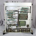
GR 1822 Inside Bottom.jpg | |||
GR 1822 Inside Bottom Card Connectors.jpg | |||
GR 1822 Inside Bottom Front Left.jpg | |||
GR 1822 Inside Bottom Front Panel.jpg | |||
GR 1822 Inside Bottom Middle Left.jpg | |||
</gallery> | |||
===Circuit Boards=== | |||
<gallery> | |||
GR 1822-2720 Component.jpg | |||
GR 1822-2720 Foil.jpg | |||
GR 1822-2731 Component.jpg | |||
GR 1822-2731 Foil.jpg | |||
GR 1822-4750 Component.jpg | |||
GR 1822-4750 Foil.jpg | |||
GR 1822-4756 Component.jpg | |||
GR 1822-4756 Foil.jpg | |||
GR 1822-4761 Component.jpg | |||
GR 1822-4761 Foil.jpg | |||
GR 1822-4766 Component.jpg | |||
GR 1822-4766 Foil.jpg | |||
GR 1822-4770 Component.jpg | |||
GR 1822-4770 Foil.jpg | |||
GR 1822-4776 Component.jpg | |||
GR 1822-4776 Foil.jpg | |||
GR 1822-4780 Component.jpg | |||
GR 1822-4780 Foil.jpg | |||
GR 1822-4785 Component.jpg | |||
GR 1822-4785 Foil.jpg | |||
GR 1822-4790 Component.jpg | |||
GR 1822-4790 Foil.jpg | |||
GR 1822-4796 Component.jpg | |||
GR 1822-4796 Foil.jpg | |||
</gallery> | </gallery> | ||
[[Category:Meters]] | [[Category:Meters]] | ||
__NOTOC__ | |||
Revision as of 20:23, 22 May 2024
The General Radio 1822 Digital Voltmeter Calibrator was available in Catalog U (1970) only.
The Type 1822 is designed to produce accurate voltages for the testing and calibration of digital voltmeters. It can be used as a precise voltage reference from 100 μV dc to 1111.1 V dc for laboratory use. The output voltage can set to any value with five digit resolution, the resolution is adjustable. The output voltage is displayed using a mechanical digital display with automatic units and decimal placement. External programming is available through a rear panel connector along with an internal automatic step function. Other features include an interference voltage function, polarity reversal, and adjustable output impedance.
Specifications
- Output Voltage: 100 μV dc to 1111.1 V dc in 7 decade ranges
- Output Impedance: <0.5 Ω on 1 V through 1 kV ranges; 200 Ω on 1 mV through 100 mV ranges; A l kΩ, 10 kΩ, or 100 kΩ output resistor can be added to above impedances by front-panel selector switch
- Output Current: 10 mA at full range on 1, 10, and 100-V ranges; 1 mA on 1 kV range
- Accuracy: ±(30 ppm of voltage + 10 ppm of full range + 3 μV) on all ranges except ±(50 ppm of voltage + 10 ppm of full range) on 1-kV range; Accuracy of rear-panel voltages ≤111 mV, ±(30 ppm of voltage + 10 ppm of range +0.5 μV)
Links
Photos
Circuit Boards


