724-A: Difference between revisions
No edit summary |
No edit summary |
||
| (3 intermediate revisions by one other user not shown) | |||
| Line 16: | Line 16: | ||
The {{Title|General Radio 724-A Precision Wavemeter}} was introduced in {{Catalog J}} and remained available through {{Catalog K4}}. | The {{Title|General Radio 724-A Precision Wavemeter}} was introduced in {{Catalog J}} and remained available through {{Catalog K4}}. | ||
The Type 724-A is an absorption type wavemeter | The Type 724-A is an absorption-type wavemeter with a range from 17 kHz to 50 MHz using seven coils with an accuracy of ±0.25%. The primary application of the 724-A is oscillator and transmitter frequency measurement. | ||
The capacitor used is similar to the | The capacitor used is similar to the [[722-N|Type 722-N Precision Capacitor]]. It is connected to the inductor through a [[774|Type 774 coaxial connector]]. | ||
Resonance is achieved using one of three methods – absorption, reaction, or beat method. | |||
Using the panel galvanometer, the absorption method is employed. | |||
Regardless of the method, once resonance is achieved, it is a matter of using the correct chart for the coil in use to determine the frequency. | |||
Type 724-A was supplied as a collection of calibrated components sharing the same serial number, i.e. the capacitor, inductors, and calibration charts must have the same serial number to achieve the stated accuracy. | |||
The 724-A replaced the [[224-A|224-A Wavemeter]] with improved coils and a galvanometer replacing the thermocouple type indicator. | |||
The wavemeter was furnished with a wooden storage case, fitted with lock and carrying handle. | |||
This case has compartments for holding the capacitor, inductors, and calibration charts. | |||
The 724-A uses a 1G4GT/G triode vacuum tube, resulting in the need for a 1.5 V battery for the heater. | |||
Note: The instrument shown in the photos below uses a 1LE3 loctal battery triode. It appears to be a production change. | |||
==Specifications== | ==Specifications== | ||
| Line 32: | Line 42: | ||
==Links== | ==Links== | ||
* [[GR Exp 724-A 03_1936.pdf|Experimenter March 1936 describing Type 724-A]] | * [[Media:GR Exp 724-A 03_1936.pdf|Experimenter March 1936 describing Type 724-A]] | ||
==Photos== | ==Photos== | ||
| Line 54: | Line 64: | ||
GR 724-A Inside Top.jpg | GR 724-A Inside Top.jpg | ||
GR 724-A Inside Bottom.jpg | GR 724-A Inside Bottom.jpg | ||
Card A SN1397.jpg | GR 724-A Case Frequency Meter.jpg | ||
GR 724-A Card A SN1397.jpg | |||
GR 724-ACard B SN1397.jpg | |||
GR 724-ACard C SN1397.jpg | |||
</gallery> | </gallery> | ||
[[Category:Frequency Standards and Meters]] | [[Category:Frequency Standards and Meters]] | ||
Latest revision as of 19:17, 30 May 2024
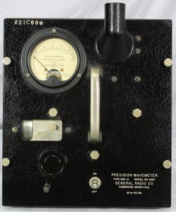
The General Radio 724-A Precision Wavemeter was introduced in Catalog J (1936) and remained available through Catalog K4 (1945).
The Type 724-A is an absorption-type wavemeter with a range from 17 kHz to 50 MHz using seven coils with an accuracy of ±0.25%. The primary application of the 724-A is oscillator and transmitter frequency measurement.
The capacitor used is similar to the Type 722-N Precision Capacitor. It is connected to the inductor through a Type 774 coaxial connector. Resonance is achieved using one of three methods – absorption, reaction, or beat method. Using the panel galvanometer, the absorption method is employed. Regardless of the method, once resonance is achieved, it is a matter of using the correct chart for the coil in use to determine the frequency.
Type 724-A was supplied as a collection of calibrated components sharing the same serial number, i.e. the capacitor, inductors, and calibration charts must have the same serial number to achieve the stated accuracy.
The 724-A replaced the 224-A Wavemeter with improved coils and a galvanometer replacing the thermocouple type indicator. The wavemeter was furnished with a wooden storage case, fitted with lock and carrying handle. This case has compartments for holding the capacitor, inductors, and calibration charts. The 724-A uses a 1G4GT/G triode vacuum tube, resulting in the need for a 1.5 V battery for the heater.
Note: The instrument shown in the photos below uses a 1LE3 loctal battery triode. It appears to be a production change.
Specifications
- Frequency Range: 16 kHz to 50 MHz using seven inductors
- Accuracy: ±0.25% between 50 kHz and 50 MHz, 1% between 16 and 50 kHz
- Inductors: 7 coils wound on isolantite forms and enclosed in molded bakelite cases
- Capacitor: Precision worm-drive type similar to Type 722
- Resonance Indicator: galvanometer and vacuum tube rectifier combination


