1401: Difference between revisions
Jump to navigation
Jump to search
(→Photos) |
No edit summary |
||
| (One intermediate revision by one other user not shown) | |||
| Line 16: | Line 16: | ||
The {{Title|General Radio 1401 Series Standard Air Capacitors}} was introduced in {{Catalog M}} and remained available through {{Catalog S}}. | The {{Title|General Radio 1401 Series Standard Air Capacitors}} was introduced in {{Catalog M}} and remained available through {{Catalog S}}. | ||
The Type 1401 series are two terminal air capacitors designed as laboratory reference or working capacitance standards. They | The Type 1401 series is comprised of four capacitor types − [[1401-A]], [[1401-B]], [[1401-C]], and [[1401-D]]. They are two-terminal air capacitors designed as laboratory reference or working capacitance standards. They feature all-aluminum construction with shielded covers. Connections are [[274|Type 274 plugs]] spaced ¾ inches on center. This spacing matches the [[716-C|Type 716-C Capacitance Bridge]], making the 1401s useful as balancing capacitors when performing substitution measurements. | ||
==Specifications== | ==Specifications== | ||
| Line 22: | Line 22: | ||
* '''Stability:''' Capacitance change is less than 0.05% per year | * '''Stability:''' Capacitance change is less than 0.05% per year | ||
* '''Residual Impedances:''' The series inductance of all units is approximately 0.05 μH | * '''Residual Impedances:''' The series inductance of all units is approximately 0.05 μH | ||
* '''Temperature Coefficient of Capacitance:''' Typically 10 to 20 ppm/C° between 20° and 70°C | * '''Temperature Coefficient of Capacitance:''' Typically 10 to 20 ppm/C° between 20° and 70°C | ||
* '''Terminals:''' Type 274 plugs, spaced ¾ inch on centers, to plug into Type 938 binding posts | * '''Terminals:''' [[274|Type 274 plugs]], spaced ¾ inch on centers, to plug into [[938-A|Type 938 binding posts]] | ||
==Links== | ==Links== | ||
| Line 43: | Line 43: | ||
==Photos== | ==Photos== | ||
<gallery> | <gallery> | ||
GR 1401-A Front A.jpg | GR 1401-A Front A.jpg | ||
GR 1401-B Front A.jpg | GR 1401-B Front A.jpg | ||
GR 1401-C Front.jpg | GR 1401-C Front.jpg | ||
GR 1401-D Close-Up. | GR 1401-D Close-Up.JPG | ||
</gallery> | </gallery> | ||
[[Category:Capacitance Standards]] | [[Category:Capacitance Standards]] | ||
Latest revision as of 00:32, 12 May 2024
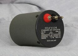
The General Radio 1401 Series Standard Air Capacitors was introduced in Catalog M (1951) and remained available through Catalog S (1965).
The Type 1401 series is comprised of four capacitor types − 1401-A, 1401-B, 1401-C, and 1401-D. They are two-terminal air capacitors designed as laboratory reference or working capacitance standards. They feature all-aluminum construction with shielded covers. Connections are Type 274 plugs spaced ¾ inches on center. This spacing matches the Type 716-C Capacitance Bridge, making the 1401s useful as balancing capacitors when performing substitution measurements.
Specifications
- Stability: Capacitance change is less than 0.05% per year
- Residual Impedances: The series inductance of all units is approximately 0.05 μH
- Temperature Coefficient of Capacitance: Typically 10 to 20 ppm/C° between 20° and 70°C
- Terminals: Type 274 plugs, spaced ¾ inch on centers, to plug into Type 938 binding posts
Links
| Type | Insertion Capacitance | Initial Accuracy | Peak Volts | Dissipation Factor | Catalog Number |
|---|---|---|---|---|---|
| 1401-A | 100 pF | 0.2% | 1500 V | 0.0001 | 1401-9701 |
| 1401-B | 200 pF | 0.15% | 1200 V | 0.00005 | 1401-9702 |
| 1401-C | 500 pF | 0.12% | 900 V | 0.00002 | 1401-9703 |
| 1401-D | 1000 pF | 0.1% | 700 V | 0.00001 | 1401-9704 |


