716-C: Difference between revisions
No edit summary |
No edit summary |
||
| (4 intermediate revisions by 2 users not shown) | |||
| Line 1: | Line 1: | ||
{{GR Product | {{GR Product | ||
|model=716-C | |model=716-C | ||
|codes=BOSOM,BONUS | |||
|class=impedance measurement | |class=impedance measurement | ||
|summary=capacitance bridge | |summary=capacitance bridge | ||
| Line 11: | Line 12: | ||
|manuals= | |manuals= | ||
* [[Media:GR 716C Capacitance Bridge 681-K 11-1959.pdf|General Radio 716-C Capacitance Bridge Manual 681-K 1959]] | * [[Media:GR 716C Capacitance Bridge 681-K 11-1959.pdf|General Radio 716-C Capacitance Bridge Manual 681-K 1959]] | ||
* [[Media:GR 716-C Capacitance Bridge 0716-0140-L 05-1963.pdf|General Radio 716-C Capacitance Bridge Manual 0716-0140-L 1963]] | |||
{{Catalog History}} | {{Catalog History}} | ||
}} | }} | ||
The {{Title|General Radio 716-C Capacitance Bridge}} was introduced in {{Catalog L}} and remained available through {{Catalog U}}. | The {{Title|General Radio 716-C Capacitance Bridge}} was introduced in {{Catalog L}} and remained available through {{Catalog U}}. | ||
The Type 716-C capacitance bridge uses the Schering circuit and is direct reading at five frequencies | The Type 716-C capacitance bridge uses the [[wikipedia:Schering bridge|Schering bridge circuit]] and is direct reading at five frequencies (100 Hz, 1 kHz, 10 kHz, and 100 kHz). Dissipation factor is direct-reading at 1 kHz but the usable range is greater, see the manual. | ||
Capacitance measurements can be made by the direct or substitution methods. When using the substitution method, a balancing capacitor is required that is 100 pF greater than the unknown, the Types [[505]] and [[509]] are recommended. Inductance and Q of large inductors can be measured by the substitution method. | |||
The 716-C requires a generator and detector, the Types [[1310-A]] or [[1311-A]] oscillators and [[1232-A]] null detector are recommended. | |||
The Type 716-C is the last instrument in 716 series being replaced by the Type [[1615-A]]. | |||
==Specifications== | ==Specifications== | ||
| Line 27: | Line 35: | ||
==Links== | ==Links== | ||
* [[Media:GR Exp 716-A 12_1936.pdf|Experimenter describing Type 716-A | * [[Media:GR Exp 716-A 12_1936.pdf|Experimenter December 1936 describing Type 716-A]] | ||
* [[Media:GR Exp 716-B 04_1942.pdf|Experimenter describing Type 716-B | * [[Media:GR Exp 716-B 04_1942.pdf|Experimenter April 1942 describing Type 716-B]] | ||
* [[Media:GR Exp 716-C 04_1947.pdf|Experimenter describing Type 716-C | * [[Media:GR Exp 716-C 04_1947.pdf|Experimenter April 1947 describing Type 716-C]] | ||
==Photos== | ==Photos== | ||
Latest revision as of 19:29, 30 May 2024
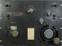
The General Radio 716-C Capacitance Bridge was introduced in Catalog L (1948) and remained available through Catalog U (1970).
The Type 716-C capacitance bridge uses the Schering bridge circuit and is direct reading at five frequencies (100 Hz, 1 kHz, 10 kHz, and 100 kHz). Dissipation factor is direct-reading at 1 kHz but the usable range is greater, see the manual.
Capacitance measurements can be made by the direct or substitution methods. When using the substitution method, a balancing capacitor is required that is 100 pF greater than the unknown, the Types 505 and 509 are recommended. Inductance and Q of large inductors can be measured by the substitution method.
The 716-C requires a generator and detector, the Types 1310-A or 1311-A oscillators and 1232-A null detector are recommended.
The Type 716-C is the last instrument in 716 series being replaced by the Type 1615-A.
Specifications
- Capacitance Range: Direct method, 100 to 1150 pF; Substitution method 0.1 to 1050 pF
- Accuracy: ±0.1%
- Dissipation Factor Range: 0.00002 to 0.56
- Accuracy: ±2%
- Frequency: 30 Hz to 300 kHz; useful up to 1 MHz with corrections
Links
- Experimenter December 1936 describing Type 716-A
- Experimenter April 1942 describing Type 716-B
- Experimenter April 1947 describing Type 716-C


