1409-Y: Difference between revisions
(Created page with "Type '''1409-Y 1.0uf Standard Capacitor'''. ==Specifications== ==Links== ==Photos== <gallery> </gallery> Category:Capacitance Standards") |
(→Photos) |
||
| (5 intermediate revisions by 2 users not shown) | |||
| Line 1: | Line 1: | ||
{{GR Product | |||
|model=1409-Y | |||
|codes=1409-1409-9725 | |||
|class=Capacitance Standards | |||
|summary=1.0μF,0.05% Standard Capacitor | |||
|image=GR 1409-Y Front.jpg | |||
|caption=General Radio 1409-Y Standard Capacitor | |||
|series=1409 | |||
|introduced=1956 | |||
|discontinued=1978+ | |||
|designers= | |||
|manuals= | |||
* '''Manual Needed.''' | |||
{{Catalog History}} | |||
}} | |||
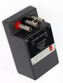
The {{Title|General Radio 1409-Y Standard Capacitor}} was introduced in {{Catalog O}} and remained available through {{Catalog 1978}}. | |||
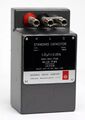
The 1409-Y is a fixed mica capacitor of very high stability for use as two- or three-terminal capacitance standard in the laboratory. | |||
The capacitor is installed in an aluminum case along with silica-gel desiccant, then sealed with high-temperature potting wax. | |||
A well located on the right side of the case allows insertion of a dial-type thermometer. | |||
Three jack-top binding posts on the top of the case and removable plugs on the bottom are provided for convenient parallel connection without error. | |||
Each capacitor is supplied with a certificate of calibration giving two- and three-terminal measured capacitance. | |||
The Type 1409-Y capacitor is mounted in the large case. | |||
See [[1409]] to view all the capacitors in the series. | |||
==Specifications== | ==Specifications== | ||
* '''Capacitance:''' 1.0 μF | |||
* '''Series Inductance:''' 0.070 μH | |||
* '''Adjustment Accuracy:''' within ±0.05% | |||
* '''Stability:''' Capacitance change is less than 0.01% per year | |||
* '''Temperature Coefficient:''' capacitance; +35 ± 10 ppm per degree between 10 °C and 70 °C | |||
* '''Dissipation Factor:''' Less than 0.0003 at 1 kHz and 23 °C (see curves). Measured dissipation factor at 1 kHz is stated in the certificate to an accuracy of ±0.00005 | |||
* '''Leakage Resistance:''' 5000 ohm-farads or 100 GΩ, whichever is the lesser | |||
* '''Maximum Voltage:''' 500 V peak below 17 kHz | |||
==Links== | ==Links== | ||
* [[Media:GR Exp 1409 07_1957.pdf|Experimenter July 1957 describing Type 1409 Series]] | |||
==Photos== | ==Photos== | ||
<gallery> | <gallery> | ||
GR 1209 Figure 1.jpg|Change in capacitance as a function of frequency for typical Type 1409 capacitors. | |||
GR 1209 Figure 2.jpg|Dissipation factor as a function of frequency. | |||
GR 1409 Technical Drawing.jpg|Technical Drawing. | |||
GR 1409-Y Front.jpg | |||
GR 1409-Y Front A.jpg | |||
GR 1409-Y Rear Large Case.jpg | |||
</gallery> | </gallery> | ||
[[Category:Capacitance Standards]] | [[Category:Capacitance Standards]] | ||
Latest revision as of 02:06, 12 July 2024

The General Radio 1409-Y Standard Capacitor was introduced in Catalog O (1956) and remained available through Catalog 1978.
The 1409-Y is a fixed mica capacitor of very high stability for use as two- or three-terminal capacitance standard in the laboratory. The capacitor is installed in an aluminum case along with silica-gel desiccant, then sealed with high-temperature potting wax.
A well located on the right side of the case allows insertion of a dial-type thermometer. Three jack-top binding posts on the top of the case and removable plugs on the bottom are provided for convenient parallel connection without error.
Each capacitor is supplied with a certificate of calibration giving two- and three-terminal measured capacitance. The Type 1409-Y capacitor is mounted in the large case.
See 1409 to view all the capacitors in the series.
Specifications
- Capacitance: 1.0 μF
- Series Inductance: 0.070 μH
- Adjustment Accuracy: within ±0.05%
- Stability: Capacitance change is less than 0.01% per year
- Temperature Coefficient: capacitance; +35 ± 10 ppm per degree between 10 °C and 70 °C
- Dissipation Factor: Less than 0.0003 at 1 kHz and 23 °C (see curves). Measured dissipation factor at 1 kHz is stated in the certificate to an accuracy of ±0.00005
- Leakage Resistance: 5000 ohm-farads or 100 GΩ, whichever is the lesser
- Maximum Voltage: 500 V peak below 17 kHz
Links
Photos
-
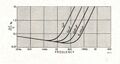
Change in capacitance as a function of frequency for typical Type 1409 capacitors.
-
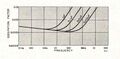
Dissipation factor as a function of frequency.
-
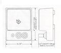
Technical Drawing.
-
-
-


