722-N: Difference between revisions
No edit summary |
No edit summary |
||
| Line 1: | Line 1: | ||
{{GR Product | {{GR Product | ||
|model=722-N | |model=722-N | ||
|codes=BOXER | |||
|class=capacitance standards | |class=capacitance standards | ||
|summary=Precision Capacitor | |summary=Precision Capacitor | ||
| Line 37: | Line 38: | ||
* [[Media:GR Exp 722 10_1938.pdf|Experimenter October 1938 describing Types 722]] | * [[Media:GR Exp 722 10_1938.pdf|Experimenter October 1938 describing Types 722]] | ||
* [https://digital.sciencehistory.org/works/t435gd03t General Radio Precision Condenser Type 722-N] @ Science and History Institute Museum Digital Collection | * [https://digital.sciencehistory.org/works/t435gd03t General Radio Precision Condenser Type 722-N] @ Science and History Institute Museum Digital Collection | ||
{{722 Series}} | |||
==Photos== | ==Photos== | ||
Latest revision as of 02:54, 4 May 2024
The General Radio 722-N Precision Capacitor was introduced in Catalog K1 (1939) and remained available through Catalog P (1959).
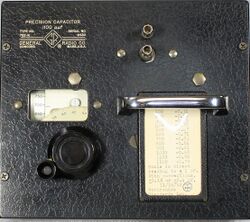
The Type 722-N is a laboratory quality, precision variable capacitor specifically designed for RF applications. It features low metallic resistance and low inductance, one third that of other 722 standard capacitors.
The set value can be read directly from a drum mounted on the rotor shaft. A correction chart is mounted on the panel for that particular capacitor.
The rotor is mounted on ball bearings in an aluminum casting and driven by a precision worm drive. It is electrically attached to the frame with silver overlay contacts.
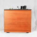
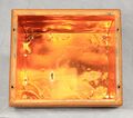
The stator is brought out to a separate terminal on the panel beside the rotor terminal attached to the chassis. The rotor terminal is a the same potential as the panel and the copper lined walnut case.
The capacitor is supplied with a fitted wooden carrying case.
Specifications
- Capacitance Range: 100 to 1100 pF
- Dial Accuracy: ±1 pF ±0.1% measured at 1 kHz
- Maximum Voltage: 1000 V peak
Links
- Experimenter February 1937 describing Types 722
- Experimenter January 1938 describing Types 722
- Experimenter October 1938 describing Types 722
- General Radio Precision Condenser Type 722-N @ Science and History Institute Museum Digital Collection
- 722-D
- 722-N
- 722-NQ
Photos
-
-
-
-
-
-
-
-
-
-
-
-
Carrying Case
-
Carrying Case


