1311-A: Difference between revisions
No edit summary |
No edit summary |
||
| (6 intermediate revisions by one other user not shown) | |||
| Line 2: | Line 2: | ||
|model=1311-A | |model=1311-A | ||
|class=oscillators | |class=oscillators | ||
|summary= | |summary=Audio oscillator | ||
|image=GR 1311-A Front.jpg | |image=GR 1311-A Front.jpg | ||
|caption=General Radio 1311-A Audio Oscillator | |caption=General Radio 1311-A Audio Oscillator | ||
| Line 10: | Line 10: | ||
|designers= | |designers= | ||
|manuals= | |manuals= | ||
* [[Media:GR 1311-A and AU Oscillator 1311-0100-D 3_1967.pdf|General Radio 1311-A and AU Audio Oscillator Manual 1311-0100-D 1967]] | |||
* [[Media:1311-A Audio Oscillator Manual.pdf|General Radio 1311-A Audio Oscillator Manual 1311-0100-C 1965]] | * [[Media:1311-A Audio Oscillator Manual.pdf|General Radio 1311-A Audio Oscillator Manual 1311-0100-C 1965]] | ||
{{Catalog History}} | |||
}} | }} | ||
The | The {{Title|General Radio 1311-A Audio Oscillator}}, a transistorized Wien-bridge audio oscillator with transformer output, was introduced in {{Catalog R}} and remained available through {{Catalog 1978}}. | ||
The switched output frequencies correspond to commonly used bridge generator frequencies. A delta frequency control is available on the front panel to fine-tune the frequency. Although designed as a bridge oscillator, the 1311-A is also well suited for audio testing, given its low hum and distortion levels. | |||
The 1311-A is part of the [[1240-A|1240-A Bridge Oscillator-Detector]]. As a bridge oscillator, it is part of the [[1660-A|1660-A Inductance Measurement System]] and the [[1620-A|1620-A Capacitance Measurement System]]. | |||
==Specifications== | ==Specifications== | ||
* '''Frequency Range:''' 11 fixed frequencies – 50, 60, 100, 120, 200, 400, | * '''Frequency Range:''' 11 fixed frequencies selected by rotary switch – 50, 60, 100, 120, 200, 400, 500 Hz; 1, 2, 5, 10 kHz; ±2% vernier | ||
* '''Power Output:''' 1 W into matched load | * '''Power Output:''' 1 W into matched load; taps provide at least 0.5 W output into any resistive load between 80 mΩ and 8 kΩ | ||
* '''Output Voltage:''' Continuously adjustable from 0 to 1, 3, 10, 30, or 100 V, open circuit | * '''Output Voltage:''' Continuously adjustable from 0 to 1, 3, 10, 30, or 100 V, open circuit | ||
* '''Output Current:''' Continuously adjustable from 0 to 40, 130, 400, 1300, 4000 mA, short circuit (approx) | * '''Output Current:''' Continuously adjustable from 0 to 40, 130, 400, 1300, 4000 mA, short circuit (approx) | ||
==Links== | ==Links== | ||
* [[Media:GR Exp 1311 08_1962.pdf|Experimenter describing Type 1311-A | * [[Media:GR Exp 1311 08_1962.pdf|Experimenter August 1962 describing Type 1311-A]] | ||
* [[Media:Electronics-1963-02-01 Ref GR 1311-A.pdf| R.G.Fulks, ''Novel feedback loop stabilizes audio oscillator''; Electronics Vol.36 No.5, 1 Feb 1963. | * [[Media:Electronics-1963-02-01 Ref GR 1311-A.pdf| R.G.Fulks, ''Novel feedback loop stabilizes audio oscillator''; Electronics Vol.36 No.5, 1 Feb 1963. | ||
]] | ]] | ||
| Line 38: | Line 42: | ||
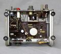
GR 1311-A Bottom.jpg | GR 1311-A Bottom.jpg | ||
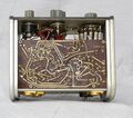
GR 1311-A Top.jpg | GR 1311-A Top.jpg | ||
GR 1240-A Close-Up.jpg | Late model, white front-panel 1311-A as part of a 1240-A | |||
</gallery> | </gallery> | ||
[[Category:Oscillators]] | [[Category:Oscillators]] | ||
[[Category:Introduced in 1963]] | [[Category:Introduced in 1963]] | ||
Latest revision as of 08:34, 17 October 2024
The General Radio 1311-A Audio Oscillator, a transistorized Wien-bridge audio oscillator with transformer output, was introduced in Catalog R (1963) and remained available through Catalog 1978.
The switched output frequencies correspond to commonly used bridge generator frequencies. A delta frequency control is available on the front panel to fine-tune the frequency. Although designed as a bridge oscillator, the 1311-A is also well suited for audio testing, given its low hum and distortion levels.
The 1311-A is part of the 1240-A Bridge Oscillator-Detector. As a bridge oscillator, it is part of the 1660-A Inductance Measurement System and the 1620-A Capacitance Measurement System.
Specifications
- Frequency Range: 11 fixed frequencies selected by rotary switch – 50, 60, 100, 120, 200, 400, 500 Hz; 1, 2, 5, 10 kHz; ±2% vernier
- Power Output: 1 W into matched load; taps provide at least 0.5 W output into any resistive load between 80 mΩ and 8 kΩ
- Output Voltage: Continuously adjustable from 0 to 1, 3, 10, 30, or 100 V, open circuit
- Output Current: Continuously adjustable from 0 to 40, 130, 400, 1300, 4000 mA, short circuit (approx)
Links
- Experimenter August 1962 describing Type 1311-A
- R.G.Fulks, Novel feedback loop stabilizes audio oscillator; Electronics Vol.36 No.5, 1 Feb 1963.
Photos
-
-
-
-
-
-
-
-
Late model, white front-panel 1311-A as part of a 1240-A


