1000-P7: Difference between revisions
Jump to navigation
Jump to search
No edit summary |
No edit summary |
||
| (11 intermediate revisions by 2 users not shown) | |||
| Line 1: | Line 1: | ||
{{GR Product | {{GR Product | ||
|model=1000-P7 | |model=1000-P7 | ||
|codes=AWAKE,1000-9607 | |||
|class=generators | |class=generators | ||
|summary= | |summary=Balanced modulator | ||
|image=GR 1000-P7 Front Close-up.jpg | |image=GR 1000-P7 Front Close-up.jpg | ||
|caption=General Radio 1000-P7 Balanced Modulator | |caption=General Radio 1000-P7 Balanced Modulator | ||
|series=1000 | |||
|introduced=1954 | |introduced=1954 | ||
|discontinued=1963 | |discontinued=1963 | ||
| Line 11: | Line 13: | ||
* [[Media:GRwiki 1000-P7 Balanced Modulator 818-A 12_1953.pdf|General Radio 1000-P7 Balanced Modulator 818-A 1953]] | * [[Media:GRwiki 1000-P7 Balanced Modulator 818-A 12_1953.pdf|General Radio 1000-P7 Balanced Modulator 818-A 1953]] | ||
{{Catalog History}} | {{Catalog History}} | ||
}} | }} | ||
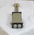
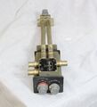
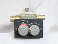
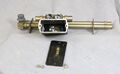
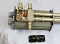
The | The {{Title|General Radio 1000-P7 Balanced Modulator}} was introduced in {{Catalog N}} and remained available through {{Catalog R}}. | ||
The Type 1000-P6 is an accessory modulator for oscillator frequencies between 60 and 2500 MHz. It uses two 1N21B microwave diodes as part of the modulator. The 1000-P6 uses three controls that require and oscilloscope to properly adjust. Using these controls the modulator provides am, double sideband suppressed carrier and pulse type modulation. The phasing adjustment is two parts, a fine control knob and coarse control by extending or retracting the "trombone" line. | |||
==Specifications== | ==Specifications== | ||
| Line 25: | Line 23: | ||
* '''Modulation-Frequency Range:''' 0 to 20 MHz. For pulsing, the rise-time contribution is less than 20 ns | * '''Modulation-Frequency Range:''' 0 to 20 MHz. For pulsing, the rise-time contribution is less than 20 ns | ||
* '''Impedance:''' source and load impedances are 50 Ω, The impedance at the modulation input is 50 ohms ±5% | * '''Impedance:''' source and load impedances are 50 Ω, The impedance at the modulation input is 50 ohms ±5% | ||
* '''Bias:''' internal battery, adjustable 0 to 3 V | * '''Bias:''' internal battery, adjustable 0 to 3 V (2 D-cells) | ||
==Links== | ==Links== | ||
| Line 41: | Line 39: | ||
GR 1000-P7 Controls.jpg | GR 1000-P7 Controls.jpg | ||
GR 1000-P7LA Front.jpg | GR 1000-P7LA Front.jpg | ||
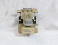
GR 1000-P7 Bias Battery Box.jpg | GR 1000-P7 Bias Battery Box.jpg|Battery Box 2 D-cells | ||
GR 1000-P7 Inside.jpg | GR 1000-P7 Inside.jpg | ||
GR 1000-P7 Inside Close-up.jpg | GR 1000-P7 Inside Close-up.jpg | ||
Latest revision as of 18:50, 16 April 2024

The General Radio 1000-P7 Balanced Modulator was introduced in Catalog N (1954) and remained available through Catalog R (1963).
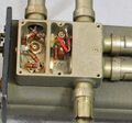
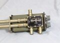
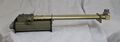
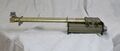
The Type 1000-P6 is an accessory modulator for oscillator frequencies between 60 and 2500 MHz. It uses two 1N21B microwave diodes as part of the modulator. The 1000-P6 uses three controls that require and oscilloscope to properly adjust. Using these controls the modulator provides am, double sideband suppressed carrier and pulse type modulation. The phasing adjustment is two parts, a fine control knob and coarse control by extending or retracting the "trombone" line.
Specifications
- Carrier Frequency Range: The useful carrier-frequency range is 60 to 2500 MHz
- Modulation-Frequency Range: 0 to 20 MHz. For pulsing, the rise-time contribution is less than 20 ns
- Impedance: source and load impedances are 50 Ω, The impedance at the modulation input is 50 ohms ±5%
- Bias: internal battery, adjustable 0 to 3 V (2 D-cells)
Links
Photos
-
-
-
-
-
-
-
-
Battery Box 2 D-cells
-
-