1001-A: Difference between revisions
(→Photos) |
No edit summary |
||
| (25 intermediate revisions by 2 users not shown) | |||
| Line 1: | Line 1: | ||
{{GR Product | |||
|model=1001-A | |||
The 1001-A is a | |codes=ARGUS,1001-9701 | ||
|class=generators | |||
|summary=Standard signal generator | |||
|image=GR 1001-A Front A.jpg | |||
|caption=General Radio 1001-A Signal Generator | |||
|series= | |||
|introduced=1951 | |||
|discontinued=1973 | |||
|designers= | |||
|manuals= | |||
* [[Media:GR 1001A Signal Generator 09_1967.pdf|General Radio 1001-A Signal Generator Manual 1001-0100-O (1967)]] | |||
{{Catalog History}} | |||
}} | |||
The {{Title|General Radio 1001-A}} is a standard signal generator introduced in {{Catalog M}}. It remained available through {{Catalog 1973}}. | |||
The 1001-A covers a frequency range of 5 kHz to 50 MHz. It has a calibrated attenuator with output 0.1 μV to 200 mV, and also 2 V direct output. | |||
The internal RF oscillator and turret band switch are removable for servicing. Inside the cabinet is a hex alignment tool for adjusting the oscillator turret coils. | |||
==Specifications== | |||
* '''Frequency Range:''' 5 kHz to 50 MHz in 8 bands | |||
* '''Accuracy:''' ±1% of reading | |||
* '''Stability:''' Warmup drift ~0.25%, half the maximum drift reached in approximately 1½ hours | |||
* '''Amplitude Modulation:''' 0 to 80%, continuously variable, indicated on the panel meter to ±10% of reading | |||
* '''Modulation Frequency:''' 400 Hz internal, 20 Hz to 15 kHz external modulation | |||
* '''Output Impedance:''' 10 Ω except at the 100 mV multiplier setting 50 Ω, 300 Ω at the 2 V output | |||
==Links== | ==Links== | ||
* [[Media:GRwiki Exp 1001-A 1949.pdf|Experimenter describing 1001-A | * [[Media:GRwiki Exp 1001-A 1949.pdf|Experimenter September 1949 describing 1001-A]] | ||
==Photos== | ==Photos== | ||
<gallery> | <gallery> | ||
GR 1001-A Front A.jpg | GR 1001-A Front A.jpg | ||
GR 1001-A Top Rear.jpg | GR 1001-A Top Rear.jpg|Top Deck | ||
GR 1001-A Bottom Rear A.jpg | GR 1001-A Bottom Rear A.jpg|Bottom Deck | ||
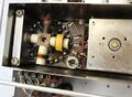
GR 1001-A RF Unit.jpg | GR 1001-A RF Unit.jpg|RF Unit (Cover Removed) | ||
GR 1001-A RF Unit Band Turret.jpg|RF Turret Switch | GR 1001-A RF Unit Band Turret.jpg|RF Turret Switch | ||
GR 1001-A RF Unit Output.jpg|Output Amplifier 6L6G | GR 1001-A RF Unit Output.jpg|Output Amplifier 6L6G | ||
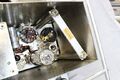
GR 1001-A Accessory Storage.jpg|Accessory Storage Area | GR 1001-A Accessory Storage.jpg|Accessory Storage Area | ||
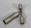
GR 1001-A Alignment Tool.jpg|Alignment Tool | GR 1001-A Alignment Tool.jpg|Alignment Tool Storage | ||
GR 1001-A Alignment Tool Close-up.jpg|TO-44 Alignment Tool | |||
</gallery> | </gallery> | ||
===Supplied Accessories=== | |||
<gallery> | |||
GR 1000-P1 Front.jpg|Type 1000-P1 50 Ω Termination | |||
GR 1000-P1 Open Front.jpg|Type 1000-P1 50 Ω Termination | |||
GR 1000-P1 Card Resistor.jpg|Type 1000-P1 50 Ω Termination | |||
GR 1000-P2 Front.jpg|Type 1000-P2 40 Ω Termination | |||
GR 1000-P2 Open.jpg|Type 1000-P2 40 Ω Termination | |||
GR 1000-P2 Card Resistor.jpg|Type 1000-P2 40 Ω Termination | |||
</gallery> | |||
[[Category:Generators]] | [[Category:Generators]] | ||
__NOTOC__ | |||
Latest revision as of 03:08, 11 May 2024

The General Radio 1001-A is a standard signal generator introduced in Catalog M (1951). It remained available through Catalog 1973.
The 1001-A covers a frequency range of 5 kHz to 50 MHz. It has a calibrated attenuator with output 0.1 μV to 200 mV, and also 2 V direct output.
The internal RF oscillator and turret band switch are removable for servicing. Inside the cabinet is a hex alignment tool for adjusting the oscillator turret coils.
Specifications
- Frequency Range: 5 kHz to 50 MHz in 8 bands
- Accuracy: ±1% of reading
- Stability: Warmup drift ~0.25%, half the maximum drift reached in approximately 1½ hours
- Amplitude Modulation: 0 to 80%, continuously variable, indicated on the panel meter to ±10% of reading
- Modulation Frequency: 400 Hz internal, 20 Hz to 15 kHz external modulation
- Output Impedance: 10 Ω except at the 100 mV multiplier setting 50 Ω, 300 Ω at the 2 V output
Links
Photos
-

-

Top Deck
-

Bottom Deck
-

RF Unit (Cover Removed)
-
RF Turret Switch
-
Output Amplifier 6L6G
-

Accessory Storage Area
-

Alignment Tool Storage
-

TO-44 Alignment Tool


Supplied Accessories
-

Type 1000-P1 50 Ω Termination
-
Type 1000-P1 50 Ω Termination
-

Type 1000-P1 50 Ω Termination
-

Type 1000-P2 40 Ω Termination
-

Type 1000-P2 40 Ω Termination
-

Type 1000-P2 40 Ω Termination


