874-GA: Difference between revisions
(Created page with "Type '''874-GA Adjustable Attenuator'''. ==Specifications== ==Links== ==Photos== <gallery> </gallery> Category:Coaxial Elements Category:GR-874") |
No edit summary |
||
| (2 intermediate revisions by 2 users not shown) | |||
| Line 1: | Line 1: | ||
{{GR Product | |||
|model=874-GA | |||
|codes=COAXLOSSER | |||
|class=coaxial elements | |||
|summary=Adjustable Attenuator | |||
|image=GR 874-GA Front A.jpg | |||
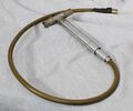
|caption=General Radio 874-GA Adjustable Attenuator | |||
|series=GR-874 | |||
|introduced=1951 | |||
|discontinued=1961 | |||
|designers= | |||
|manuals= | |||
* [[Media:GR 874-GA Adjustable Attenuator 0874-0210-I 06-1968.pdf|General Radio 874-GA Adjustable Attenuator Manual 0874-0210-I 1968]] | |||
{{Catalog History}} | |||
}} | |||
The {{Title|General Radio 874-GA Adjustable Attenuator}} was introduced in {{Catalog M}} and remained available through {{Catalog Q}}. | |||
The Type 874-GA is a mutual-inductance (waveguide-below-cutoff) type attenuator. A micrometer-type barrel adjusts the distance between a pick-up loop attached to a three-foot coaxial cable and the short section of the input coaxial line. Both the barrel and adjusting sleeve are calibrated in decibels, one turn produces a change of 20 dB for a total or 120 dB of attenuation. Used with other coaxial elements the such as the [[874-VI|874-VI Voltmeter Indicator]] or the [[874-VR|874-VR Voltmeter Rectifier]], the 874-GA can be used to attenuate and monitor signal generators and oscillators. The attenuator can also be used to measure the attenuation of a network by the substitution method. | |||
==Specifications== | ==Specifications== | ||
* '''Calibrated Range:''' 120 dB | |||
* '''Insertion Loss''': | |||
** At beginning of calibrated range: Approximately inversely proportional to frequency up to 1 GHz; approximately 20 dB at 1 GHz with tuned input; approximately 33 dB with input line terminated in 50 Ω | |||
** Outside of calibrated range: Approximately inversely proportional to frequency; approximately 18 dB at 1 GHz | |||
* '''Accuracy of Attenuation:''' ±0.5 dB when corrected | |||
* '''Frequency Range:''' 100 MHz to 3 GHz | |||
* '''Waveguide Mode:''' TE<sub>1,1</sub>; cutoff frequency 12.3 GHz | |||
==Links== | ==Links== | ||
* [[Media:GR Exp 874-GA 01_1950.pdf|Experimenter January 1950 describing Type 874-GA]] | |||
==Photos== | ==Photos== | ||
<gallery> | <gallery> | ||
GR 874-GA Front A.jpg | |||
GR 874-GA Close-up A.jpg | |||
GR 874-GA Close-up C.jpg | |||
GR 874-GA Close-up.jpg | |||
</gallery> | </gallery> | ||
[[Category:Coaxial Elements]] | [[Category:Coaxial Elements]] | ||
[[Category:GR-874]] | [[Category:GR-874]] | ||
Latest revision as of 00:03, 13 May 2024
The General Radio 874-GA Adjustable Attenuator was introduced in Catalog M (1951) and remained available through Catalog Q (1961).
The Type 874-GA is a mutual-inductance (waveguide-below-cutoff) type attenuator. A micrometer-type barrel adjusts the distance between a pick-up loop attached to a three-foot coaxial cable and the short section of the input coaxial line. Both the barrel and adjusting sleeve are calibrated in decibels, one turn produces a change of 20 dB for a total or 120 dB of attenuation. Used with other coaxial elements the such as the 874-VI Voltmeter Indicator or the 874-VR Voltmeter Rectifier, the 874-GA can be used to attenuate and monitor signal generators and oscillators. The attenuator can also be used to measure the attenuation of a network by the substitution method.
Specifications
- Calibrated Range: 120 dB
- Insertion Loss:
- At beginning of calibrated range: Approximately inversely proportional to frequency up to 1 GHz; approximately 20 dB at 1 GHz with tuned input; approximately 33 dB with input line terminated in 50 Ω
- Outside of calibrated range: Approximately inversely proportional to frequency; approximately 18 dB at 1 GHz
- Accuracy of Attenuation: ±0.5 dB when corrected
- Frequency Range: 100 MHz to 3 GHz
- Waveguide Mode: TE1,1; cutoff frequency 12.3 GHz


