1650-B: Difference between revisions
Jump to navigation
Jump to search
(Created page with "Type '''1650-B Impedance Bridge'''. ==Specifications== ==Links== ==Photos== <gallery> </gallery> Category:Impedance measurement") |
No edit summary |
||
| (18 intermediate revisions by 2 users not shown) | |||
| Line 1: | Line 1: | ||
{{GR Product | |||
|model=1650-B | |||
|class=impedance measurement | |||
|summary=Impedance bridge | |||
|image=GR 1650-B Front A.jpg | |||
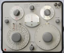
|caption=General Radio 1650-B Impedance Bridge | |||
|series= | |||
|introduced=1968 | |||
|discontinued=1978+ | |||
|designers=Henry P. Hall | |||
|manuals= | |||
* [[Media:GRwiki 1650-B Impedance Bridge 1650-0120-8 08_1970.pdf|General Radio 1650-B Impedance Bridge 1650-0120-8 08_1970]] | |||
* [[Media:GRwiki 1650-B Impedance Bridge 1650-0120-A 04-1968.pdf|General Radio 1650-B Impedance Bridge 1650-120-A 04-1968]] | |||
{{Catalog History}} | |||
}} | |||
The {{Title|General Radio 1650-B Impedance Bridge}} was introduced in {{Catalog T}} and remained available through {{Catalog 1978}}. | |||
The Type 1650-B is the improved version of the iconic [[1650-A]] with specifications similar to its predecessor. | |||
Improvements include an added conductance bridge, slow motion dials for DQ and RCL, battery check setting on the function switch, and a side panel for connections preciously on the front panel. | |||
The battery compartment was redesigned, with the batteries contained in a removeable tube that is accessible after removing the bridge from its case. | |||
The 1650-B also features the "[[Orthonull]]" device that helps prevent a sliding null (see [[1650-A]]). | |||
==Specifications== | ==Specifications== | ||
* '''Capacitance:''' 1 pF to 1100 μF in 7 ranges | |||
* '''Inductance:''' 1 μH to 1100 H in 7 ranges | |||
* '''Resistance:''' 1 mΩ to 1.1 MΩ in 7 ranges | |||
* '''Conductance:''' AC or DC, 1 nS to 1.1 S in 7 ranges | |||
* '''D:''' (series capacitance) 0.001 to 1 at 1 kHz, (parallel capacitance) 0.1 to 50 at 1 kHz | |||
* '''Q:''' (series inductance) 0.02 to 10 at 1 kHz, (parallel inductance) 1 to 1000 at 1 kHz | |||
* '''Basic accuracy:''' ±1% of full scale, ±5% for dissipation factor | |||
* '''Internal oscillator:''' 1 kHz ±2% | |||
* '''Frequency range:''' 20 Hz to 20 kHz (to 100 kHz with reduced accuracy) | |||
==Links== | ==Links== | ||
* [[Media:GR Exp 1650-B 05_1968.pdf|Experimenter May 1968 describing Type 1650-B]] | |||
==Photos== | ==Photos== | ||
<gallery> | <gallery> | ||
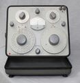
GR 1650-B Front.jpg | |||
GR 1650-B Left.jpg | |||
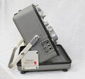
GR 1650-B Right.jpg | |||
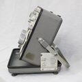
GR 1650-B Bottom A.jpg | |||
GR 1650-B Bottom B.jpg | |||
GR 1650-B Rear A.jpg | |||
GR 1650-B Rear B.jpg | |||
GR 1650-B Rear.jpg | |||
GR 1650-B Top A.jpg | |||
GR 1650-B Top B.jpg | |||
GR 1650-B Top Right.jpg | |||
GR 1650-B Board Close-up.jpg | |||
</gallery> | </gallery> | ||
[[Category:Impedance measurement]] | [[Category:Impedance measurement]] | ||
Latest revision as of 03:03, 16 April 2024
The General Radio 1650-B Impedance Bridge was introduced in Catalog T (1968) and remained available through Catalog 1978.
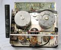
The Type 1650-B is the improved version of the iconic 1650-A with specifications similar to its predecessor. Improvements include an added conductance bridge, slow motion dials for DQ and RCL, battery check setting on the function switch, and a side panel for connections preciously on the front panel. The battery compartment was redesigned, with the batteries contained in a removeable tube that is accessible after removing the bridge from its case.
The 1650-B also features the "Orthonull" device that helps prevent a sliding null (see 1650-A).
Specifications
- Capacitance: 1 pF to 1100 μF in 7 ranges
- Inductance: 1 μH to 1100 H in 7 ranges
- Resistance: 1 mΩ to 1.1 MΩ in 7 ranges
- Conductance: AC or DC, 1 nS to 1.1 S in 7 ranges
- D: (series capacitance) 0.001 to 1 at 1 kHz, (parallel capacitance) 0.1 to 50 at 1 kHz
- Q: (series inductance) 0.02 to 10 at 1 kHz, (parallel inductance) 1 to 1000 at 1 kHz
- Basic accuracy: ±1% of full scale, ±5% for dissipation factor
- Internal oscillator: 1 kHz ±2%
- Frequency range: 20 Hz to 20 kHz (to 100 kHz with reduced accuracy)
