720-A: Difference between revisions
Jump to navigation
Jump to search
No edit summary |
No edit summary |
||
| (2 intermediate revisions by 2 users not shown) | |||
| Line 1: | Line 1: | ||
{{GR Product | {{GR Product | ||
|model=720-A | |model=720-A | ||
|codes=FANCY | |||
|class=frequency standards and meters | |class=frequency standards and meters | ||
|summary=Frequency Meter | |summary=Frequency Meter | ||
| Line 8: | Line 9: | ||
|introduced=1945 | |introduced=1945 | ||
|discontinued=1959 | |discontinued=1959 | ||
|designers= | |designers=Eduard Karplus | ||
|manuals= | |manuals= | ||
* [[Media:720-A Frequency Meter.pdf|General Radio 720-A Manual]] | * [[Media:720-A Frequency Meter.pdf|General Radio 720-A Manual]] | ||
| Line 25: | Line 26: | ||
==Links== | ==Links== | ||
* [[Media:GR Exp 720-A 07_1945.pdf|Experimenter describing Type 720-A | * [[Media:GR Exp 720-A 07_1945.pdf|Experimenter July 1945 describing Type 720-A]] | ||
* [[Media:Grid Bias Cells.jpg|Bias Cell Data]] | * [[Media:Grid Bias Cells.jpg|Bias Cell Data]] | ||
* [[Media:1N Series Microwave Diode Data Sheet.pdf|1N21B Microwave Diode Data]] | * [[Media:1N Series Microwave Diode Data Sheet.pdf|1N21B Microwave Diode Data]] | ||
| Line 43: | Line 44: | ||
GR 720-A Top A.jpg | GR 720-A Top A.jpg | ||
GR 720-A Top.jpg | GR 720-A Top.jpg | ||
GR 720-A Schematic Inside A.jpg | |||
</gallery> | </gallery> | ||
[[Category:Frequency Standards and Meters]] | [[Category:Frequency Standards and Meters]] | ||
Latest revision as of 19:28, 30 May 2024
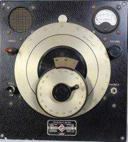
The General Radio 720-A Frequency Meter was introduced in Catalog K4 (1945) and remained available through Catalog P (1959).
The Type 720-A is a heterodyne type frequency meter using a calibrated oscillator from 100 to 200 MHz. Using harmonics frequency measurement from 10 MHz to 3 GHz are possible. Using a built in antenna to couple the unknown a zero beat can be obtained and monitored. The beat note is displayed on a panel meter and heard with an internal speaker. The 720-A can be powered by Burgess 6TA60 battery or the Type 1261-A power supply. "Bias Cells" provide grid bias potentials B1 and B2. See "Bias Cell" information below.
Specifications
- Frequency Range: Fundamental frequcncy range is from 100 to 200 MHz. harmonics 10 to 3000 MHz
- Calibration: The main dial is calibrated in frequency, each division corresponding to 1 MHz
- Accuracy: The overall accuracy of measurement is 0.1 %
Links
Photos
-
-
-
-
-
-
-
1261-A Power Supply Installed
-
-
-
-
-
-


