1263-A: Difference between revisions
No edit summary |
No edit summary |
||
| (2 intermediate revisions by one other user not shown) | |||
| Line 1: | Line 1: | ||
{{GR Product | |||
|model=1263-A | |||
|codes=SALON | |||
|class=power supplies | |||
|summary=Amplitude-Regulating Power Supply | |||
|image=GR 1263-A Close-Up.jpg | |||
|caption=General Radio 1263-A Amplitude-Regulating Power Supply | |||
|series=1263 | |||
|introduced=1956 | |||
|discontinued=1959 | |||
|designers= | |||
|manuals= | |||
* [[Media:GR 1263A Amplitude Regulated Power Supply 822-A 05_1955.pdf|General Radio 1263-A Amplitude-Regulating Power Supply Manual 822-A 1955]] | |||
{{Catalog History}} | |||
}} | |||
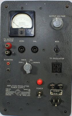
The {{Title|General Radio 1263-A Amplitude-Regulating Power Supply}} was introduced in {{Catalog O}} and remained available through {{Catalog P}}. | |||
The Type 1263-A is a power supply designed to maintain the output level of an the attached oscillator. Although compatible with most [[unit oscillators]], any oscillator with similar power requirements can be used. | |||
The 1263-A performs this by monitoring the RF output, then adjusting the oscillator's plate supply to maintain a constant amplitude. | |||
A two-pin Jones modulation connector is provided for unit oscillators requiring it for RF control. | |||
A Jones to phone jack adapter cable is required for those unit oscillators. | |||
RF monitoring is accomplished with the Type [[874-VR|874-VR Voltmeter Rectifier]] connection. Front-panel blanking connections are provided for sweep operation using Type [[1750-A]]. | |||
The 1263-A paired with the [[1750-A]] and a unit oscillator of interest are used to create an oscilloscope display for the device under test. | |||
==Specifications== | ==Specifications== | ||
* '''Output Plate Supply:''' 250 V at 25 mA | |||
* '''Output Heater Supply;''' 6 V<sub>DC</sub> at 500 mA | |||
* '''RF output regulation:''' 0.2 to 2 V with 2% accuracy | |||
* '''Response time:''' 3 mA per 3 ms output correction rate | |||
==Links== | ==Links== | ||
* [[Media:GR Exp 1750-A 04_1955.pdf|Experimenter April 1955 describing Type 1750-A]] | |||
==Photos== | ==Photos== | ||
<gallery> | <gallery> | ||
GR 1263-A Front.jpg | |||
GR 1263-A Side.jpg | |||
GR 1263-A Rear.jpg | |||
GR 1263-A Case Inside.jpg | |||
GR 1263-A Case Inside Label.jpg | |||
GR 1263-A Inside Top.jpg | |||
GR 1263-A Inside Rear.jpg | |||
GR 1263-A Inside Bottom A.jpg | |||
GR 1263-A Inside Bottom.jpg | |||
GR 1263-A Inside Bottom B.jpg | |||
GR 1263-A Inside End.jpg | |||
</gallery> | </gallery> | ||
[[Category:Power Supplies]] | [[Category:Power Supplies]] | ||
Revision as of 18:41, 24 May 2024
The General Radio 1263-A Amplitude-Regulating Power Supply was introduced in Catalog O (1956) and remained available through Catalog P (1959).
The Type 1263-A is a power supply designed to maintain the output level of an the attached oscillator. Although compatible with most unit oscillators, any oscillator with similar power requirements can be used.
The 1263-A performs this by monitoring the RF output, then adjusting the oscillator's plate supply to maintain a constant amplitude. A two-pin Jones modulation connector is provided for unit oscillators requiring it for RF control. A Jones to phone jack adapter cable is required for those unit oscillators.
RF monitoring is accomplished with the Type 874-VR Voltmeter Rectifier connection. Front-panel blanking connections are provided for sweep operation using Type 1750-A.
The 1263-A paired with the 1750-A and a unit oscillator of interest are used to create an oscilloscope display for the device under test.
Specifications
- Output Plate Supply: 250 V at 25 mA
- Output Heater Supply; 6 VDC at 500 mA
- RF output regulation: 0.2 to 2 V with 2% accuracy
- Response time: 3 mA per 3 ms output correction rate


