1454-AH: Difference between revisions
Jump to navigation
Jump to search
No edit summary |
No edit summary |
||
| (5 intermediate revisions by 2 users not shown) | |||
| Line 1: | Line 1: | ||
{{GR Product | |||
|model=1454-AH | |||
|codes=ABASH | |||
|class=resistance standards | |||
|summary=Decade Voltage Divider | |||
|image=GR 1454-AH Close-Up.jpg | |||
|caption=General Radio 1454-AH Decade Voltage Divider | |||
|series=1454 | |||
|introduced=1959 | |||
|discontinued=1965 | |||
|designers= | |||
|manuals= | |||
* [[Media:GR 1454-A_AH Decade Voltage Divider 1454-0110-E 11_1964.pdf|General Radio 1454-AH Decade Voltage Divider Manual 1454-0110-E 1964]] | |||
{{Catalog History}} | |||
}} | |||
The {{Title|General Radio 1454-AH Decade Voltage Divider}} was introduced in {{Catalog P}} and remained available through {{Catalog S}}. | |||
Type 1454-AH is a four-stage voltage divider using the [[wikipedia:Kelvin–Varley divider|Kelvin–Varley divider]] circuit. The use of four special [[510|Type 510 resistance units]] achieve this. It features a constant 100 kΩ input resistance, with a maximum input voltage of 700 V at audio frequencies. | |||
Applications for the 1454-AH include voltmeter calibration, measurements of gain and attenuation, and turns ratio of transformers. | |||
Type 1454-AH is identical to the Type [[1454-A]] except that all resistance values are increased by a factor of 10. Ungrounded or grounded operation is possible with a link at the input terminals. | |||
==Specifications== | ==Specifications== | ||
* '''Voltage Ratio:''' 0.0001 to 1.0000 in steps of 0.0001 | |||
* '''Accuracy:''' ±0.04% of indicated ratio | |||
* '''Frequency Characteristics:''' frequency error is <0.1% at 2 kHz if the external capacitance placed across the output terminals is less than 50 pF | |||
* '''Input Resistance:''' 100 kΩ | |||
* '''Output Resistance:''' Varies with output setting | |||
* '''Maximum Input Voltage:''' 700 V<sub>RMS</sub>, limited to 350 V<sub>RMS</sub> for maximum accuracy | |||
==Links== | ==Links== | ||
* [[Media:GR Exp 1454-A_AH 07_1959.pdf|Experimenter July 1959 describing Type 1454-AH]] | |||
==Photos== | ==Photos== | ||
<gallery> | <gallery> | ||
GR 1454-AH Front.jpg | |||
GR 1454-AH Bottom.jpg | |||
GR 1454-AH Left Side.jpg | |||
GR 1454-AH Rear.jpg | |||
GR 1454-AH Inside Top.jpg | |||
GR 1454-AH Inside Rear.jpg | |||
GR 1454-AH Inside Bottom.jpg | |||
</gallery> | |||
===Divide by 0.1 Unit=== | |||
<gallery> | |||
GR 1454-AH Inside Top Decade 1.jpg | |||
GR 1454-AH Inside Rear Decade 1.jpg | |||
GR 1454-AH Inside Bottom Decade 1.jpg | |||
</gallery> | |||
===Divide by 0.01 Unit=== | |||
<gallery> | |||
GR 1454-AH Inside Top Decade 2.jpg | |||
GR 1454-AH Inside Rear Decade 2.jpg | |||
GR 1454-AH Inside Bottom Decade 2.jpg | |||
</gallery> | </gallery> | ||
===Divide by 0.001 Unit=== | |||
<gallery> | |||
GR 1454-AH Inside Top Decade 3.jpg | |||
GR 1454-AH Inside Rear Decade 3.jpg | |||
GR 1454-AH Inside Bottom Decade 3.jpg | |||
</gallery> | |||
===Divide by 0.0001 Unit=== | |||
<gallery> | |||
GR 1454-AH Inside Top Decade 4.jpg | |||
GR 1454-AH Inside Rear Decade 4.jpg | |||
GR 1454-AH Inside Bottom Decade 4.jpg | |||
</gallery> | |||
[[Category:Resistance Standards]] | [[Category:Resistance Standards]] | ||
__NOTOC__ | |||
Latest revision as of 11:56, 18 May 2024
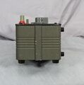
The General Radio 1454-AH Decade Voltage Divider was introduced in Catalog P (1959) and remained available through Catalog S (1965).
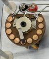
Type 1454-AH is a four-stage voltage divider using the Kelvin–Varley divider circuit. The use of four special Type 510 resistance units achieve this. It features a constant 100 kΩ input resistance, with a maximum input voltage of 700 V at audio frequencies.
Applications for the 1454-AH include voltmeter calibration, measurements of gain and attenuation, and turns ratio of transformers.
Type 1454-AH is identical to the Type 1454-A except that all resistance values are increased by a factor of 10. Ungrounded or grounded operation is possible with a link at the input terminals.
Specifications
- Voltage Ratio: 0.0001 to 1.0000 in steps of 0.0001
- Accuracy: ±0.04% of indicated ratio
- Frequency Characteristics: frequency error is <0.1% at 2 kHz if the external capacitance placed across the output terminals is less than 50 pF
- Input Resistance: 100 kΩ
- Output Resistance: Varies with output setting
- Maximum Input Voltage: 700 VRMS, limited to 350 VRMS for maximum accuracy


