1124: Difference between revisions
No edit summary |
No edit summary |
||
| Line 1: | Line 1: | ||
{{GR Product | |||
|model=1124 | |||
|codes= | |||
|class=frequency standards and meters | |||
|summary=Time signal receiver | |||
|image=Gr 1124 front2.jpg | |||
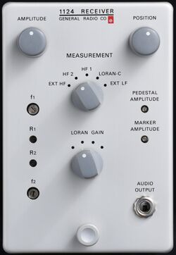
|caption=General Radio 1124 Time Receiver | |||
|series= | |||
|introduced=1968 | |||
|discontinued= | |||
|designers= | |||
|manuals= | |||
* [[Media:General Radio 1124-0100-A Jan 1969.pdf|General Radio 1124-0100-A Jan 1969.pdf]] | |||
{{Catalog History}} | |||
}} | |||
The {{Title|General Radio 1124 Time Signal Receiver}} was available in {{catalog T}} only. It is a Time Broadcast Receiver System consisting of a modified [[tekwiki:RM564|Tektronix RM564 storage oscilloscope mainframe]] with a [[tekwiki:2B67|Tektronix 2B67 time base]], and a GenRad-made receiver plug-in. Antenna connections to the receiver are routed through the rear of the modified oscilloscope mainframe. | |||
The instrument came with five receiver circuit boards for RF frequencies of 2.5, 3.33, 5.0, 7.335, and 10 MHz, respectively, any two of which could be installed in the receiver module at the same time, in addition to a Loran-C (100 kHz) receiver board and an IF amplifier board that occupy two more sockets. | |||
The 1124 is designed to work with a [[1123-A|GR 1123-A Digital Syncronometer]] (a time comparator with a 6-digit Nixie clock display) and a [[1115-B|GR 1115-B 5 MHz/1 MHz/100 kHz Standard Frequency Oscillator]] based on an OCXO. | |||
The oscilloscope is used to align reference pulses produced by the 1123 with the received signal. | |||
==Specifications== | ==Specifications== | ||
==Links== | ==Links== | ||
* [ | * [[tekwiki:General Radio 1124|General Radio 1124]] @ TekWiki | ||
* [[1124-P1]] antenna | |||
==Photos== | ==Photos== | ||
<gallery> | <gallery> | ||
Gr 1124 front2.jpg | |||
Gr 1124 right.jpg | |||
Gr 1124 left.jpg | |||
<!--Gr 1124 cards.jpg--> | |||
Gr 1124 cards2.jpg | |||
Gr 1124 5MHz 1.jpg | |||
Gr 1124 5MHz 2.jpg | |||
Gr 1125 5MHz rear.jpg | |||
Gr 1124 output amp.jpg | |||
Gr 1124 rear.jpg | |||
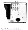
GenRad 1124 manual RM564 mod rear.png | Modified rear panel of [[tekwiki:RM564|RM564 scope]] provided by GenRad as part of 1124 receiver setup | |||
</gallery> | </gallery> | ||
[[Category:Frequency Standards and Meters]] | [[Category:Frequency Standards and Meters]] | ||
Revision as of 05:41, 17 May 2024
The General Radio 1124 Time Signal Receiver was available in Catalog T (1968) only. It is a Time Broadcast Receiver System consisting of a modified Tektronix RM564 storage oscilloscope mainframe with a Tektronix 2B67 time base, and a GenRad-made receiver plug-in. Antenna connections to the receiver are routed through the rear of the modified oscilloscope mainframe.
The instrument came with five receiver circuit boards for RF frequencies of 2.5, 3.33, 5.0, 7.335, and 10 MHz, respectively, any two of which could be installed in the receiver module at the same time, in addition to a Loran-C (100 kHz) receiver board and an IF amplifier board that occupy two more sockets.
The 1124 is designed to work with a GR 1123-A Digital Syncronometer (a time comparator with a 6-digit Nixie clock display) and a GR 1115-B 5 MHz/1 MHz/100 kHz Standard Frequency Oscillator based on an OCXO.
The oscilloscope is used to align reference pulses produced by the 1123 with the received signal.
Specifications
Links
- General Radio 1124 @ TekWiki
- 1124-P1 antenna
Photos
-
-
-
-
-
-
-
-
-
-
Modified rear panel of RM564 scope provided by GenRad as part of 1124 receiver setup


