1900-A: Difference between revisions
(Created page with "Type '''1900-A Wave Analyzer'''. ==Specifications== ==Links== ==Photos== <gallery> </gallery> Category:Wave Analyzer") |
No edit summary |
||
| (4 intermediate revisions by 2 users not shown) | |||
| Line 1: | Line 1: | ||
Type | {{GR Product | ||
|model=1900-A | |||
|codes=1900-9801 | |||
|class=wave analyzer | |||
|summary=Wave Analyzer | |||
|image=GR 1900-A Close-Up.jpg | |||
|caption=General Radio 1900-A Wave Analyzer | |||
|series=1900 | |||
|introduced=1963 | |||
|discontinued=1973 | |||
|designers= | |||
|manuals= | |||
* [[Media:GR 1900-A Wave Analyzer 1900-0100-A 05_1965.pdf|General Radio 1900-A Wave Analyzer Manual 1900-0100-A 1965]] | |||
{{Catalog History}} | |||
}} | |||
The {{Title|General Radio 1900-A Wave Analyzer}} was introduced in {{Catalog R}} and remained available through {{Catalog 1973}}. | |||
The Type 1900-A Wave Analyzer is designed to measure and analyze electrical signals between 20 Hz and 54 kHz at bandwidths as narrow as 3 Hz. | |||
It has a built-in tracking generator whose frequency is synchronized with the analyzer frequency. | |||
This generator can be used as a source for bridges or networks, and the output can be measured with high selectivity to reduce noise and harmonics. | |||
Applications include analyzing filters and frequency response of amplifiers or networks. | |||
When coupled with a [[1521-B|Type 1521-B Graphic Level Recorder]], a permanent record of the spectrum of interest can be produced. | |||
The combination of 1900-A and 1521-B make up the [[1910|Type 1910 Recording Wave Analyzer]]. | |||
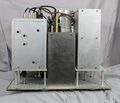
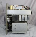
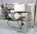
The 1900-A is a complex instrument but major components are housed in their respective shielded enclosures. | |||
These sub-assemblies are connected using RCA and Jones type connectors, simplifying service. | |||
==Specifications== | ==Specifications== | ||
* '''Frequency Range:''' 20 to 54,000 Hz | |||
* '''Accuracy of Calibration:''' ±(½% +5 Hz) up to 50 kHz;. ±1% beyond 50 kHz | |||
* '''Incremental Frequency Dial (ΔF):''' ±100 Hz. accuracy is ±2 Hz below 2 kHz, ±5 Hz up to 50 kHz | |||
* '''Selectivity:''' three bandwidths (3, 10, and 50 Hz) selected by switch | |||
* '''Input Impedance:''' 1 MΩ on all ranges | |||
* '''Input Voltage Range:''' 30 μV to 300 V full scale | |||
==Links== | ==Links== | ||
* [[Media:GR Exp 1900-A 04_1964.pdf|Experimenter April 1964 describing Type 1900-A]] | |||
* [[Media:GR Exp 1900-A 08_1966.pdf|Experimenter August 1966 describing Type 1900-A]] | |||
* [[1910]] | |||
==Photos== | ==Photos== | ||
<gallery> | <gallery> | ||
GR-1910-ad-Electronics-1969-10-04.jpg | |||
GR 1900-A Front.jpg | |||
GR 1900-A Case Side.jpg | |||
GR 1900-A Case Rear.jpg | |||
GR 1900-A Case Rear Close-Up.jpg | |||
</gallery> | |||
===Top View=== | |||
<gallery> | |||
GR 1900-A 1 Inside Top.jpg | |||
GR 1900-A 2 Inside Top Left.jpg | |||
GR 1900-A 3 Inside Top Center.jpg | |||
GR 1900-A 4 Inside Top Right.jpg | |||
GR 1900-A 5 Inside Top Center Close-up.jpg | |||
</gallery> | |||
===Left View=== | |||
<gallery> | |||
GR 1900-A 1 Inside Left Side.jpg | |||
GR 1900-A 2 Inside Rear Board B.jpg | |||
GR 1900-A 3 Inside Bottom Left Board.jpg | |||
GR 1900-A 4 Inside Bottom Board A.jpg | |||
GR 1900-A 5 Inside Left Upper.jpg | |||
</gallery> | |||
===Right View=== | |||
<gallery> | |||
GR 1900-A 1 Inside Right Side.jpg | |||
GR 1900-A 2 Inside Right Top.jpg | |||
GR 1900-A 3 Inside Right upper.jpg | |||
GR 1900-A 4 Inside Right Lower.jpg | |||
GR 1900-A 5 Inside Left Side Open.jpg | |||
</gallery> | |||
===Bottom View=== | |||
<gallery> | |||
GR 1900-A 1 Inside Bottom.jpg | |||
GR 1900-A 2 Inside Bottom Right.jpg | |||
GR 1900-A 3 Inside Bottom Left Close-Up.jpg | |||
GR 1900-A 4 Inside Bottom Left.jpg | |||
GR 1900-A 5 Inside Bottom Left Open.jpg | |||
GR 1900-A 6 Inside Bottom Open.jpg | |||
GR 1900-A 7 Inside Bottom Left Open A.jpg | |||
GR 1900-A 8 Inside Bottom Right Open.jpg | |||
</gallery> | |||
===Rear View=== | |||
<gallery> | |||
GR 1900-A 1 Inside Rear Left.jpg | |||
GR 1900-A 2 Inside Rear Right Upper.jpg | |||
GR 1900-A 3 Inside Upper Left.jpg | |||
GR 1900-A 4 Inside Rear Center.jpg | |||
GR 1900-A 5 Inside Rear Upper Right.jpg | |||
GR 1900-A 6 Inside Rear Lower Right.jpg | |||
GR 1900-A 7 Inside Rear Right.jpg | |||
</gallery> | </gallery> | ||
[[Category:Wave Analyzer]] | [[Category:Wave Analyzer]] | ||
__NOTOC__ | |||
Latest revision as of 06:34, 14 May 2024
The General Radio 1900-A Wave Analyzer was introduced in Catalog R (1963) and remained available through Catalog 1973.
The Type 1900-A Wave Analyzer is designed to measure and analyze electrical signals between 20 Hz and 54 kHz at bandwidths as narrow as 3 Hz. It has a built-in tracking generator whose frequency is synchronized with the analyzer frequency. This generator can be used as a source for bridges or networks, and the output can be measured with high selectivity to reduce noise and harmonics.
Applications include analyzing filters and frequency response of amplifiers or networks.
When coupled with a Type 1521-B Graphic Level Recorder, a permanent record of the spectrum of interest can be produced. The combination of 1900-A and 1521-B make up the Type 1910 Recording Wave Analyzer.
The 1900-A is a complex instrument but major components are housed in their respective shielded enclosures. These sub-assemblies are connected using RCA and Jones type connectors, simplifying service.
Specifications
- Frequency Range: 20 to 54,000 Hz
- Accuracy of Calibration: ±(½% +5 Hz) up to 50 kHz;. ±1% beyond 50 kHz
- Incremental Frequency Dial (ΔF): ±100 Hz. accuracy is ±2 Hz below 2 kHz, ±5 Hz up to 50 kHz
- Selectivity: three bandwidths (3, 10, and 50 Hz) selected by switch
- Input Impedance: 1 MΩ on all ranges
- Input Voltage Range: 30 μV to 300 V full scale
Links


