1231-B: Difference between revisions
No edit summary |
No edit summary |
||
| (One intermediate revision by the same user not shown) | |||
| Line 1: | Line 1: | ||
{{GR Product | |||
|model=1231-B | |||
|codes=VALID,VENUS,VALOR,VIGIL,VIGOR,VILLA | |||
|class=detectors amplifiers | |||
|summary=Amplifier and Null Detector | |||
|image=GR 1231-B Close-Up.jpg | |||
|caption=General Radio 1231-B Amplifier and Null Detector | |||
|series=1231 | |||
|introduced=1948 | |||
|discontinued=1959 | |||
|designers= | |||
|manuals= | |||
* [[Media:GR 1231-B Amplifier and Null Detector 634-H 05_1961.pdf|General Radio 1231-B Amplifier and Null Detector 634-H 1961]] | |||
{{Catalog History}} | |||
}} | |||
The {{Title|General Radio 1231-B Amplifier and Null Detector}} was introduced in {{Catalog L}} and remained available through {{Catalog P}}. | |||
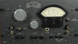
The Type 1231-B is a combination three stage hi-gain amplifier and dual range null detector. The first stage of the amplifier uses a two step attenuator, the second stage introduces variable gain control, finally the third stage applies tuning filters and amplification. The null detector or voltmeter has two ranges using push-buttons or can be disabled. The panel meter has two scales, voltage and decibels along with a battery check function. The 1231-B is designed for battery operation or AC operation using the Type [[1261-A]] power supply. Regardless of power supply used the amplifier bias supply is provided by "Bias Cells". | |||
A front panel phone jack is available for filters to apply to the amplifier. | |||
Accessory filters [[1231-P2]] 60 Hz, [[1231-P3]] 400 and 1000 Hz are available to tune the amplifier to those frequencies. The Type [[1231-P5]] variable filter covers 50 Hz to 100 kHz. To adapt the 1231-B for use with a slotted line the Type [[1231-P4]] adjustable attenuator is used for standing-wave ratio measurements. Caution: When using the [[1261-A]] power supply, the 1231-A must be switched on and an external switch must be used to control the power supply. | |||
==Specifications== | ==Specifications== | ||
* '''Input Impedance:''' 1 MΩ in parallel with 20 pF; alternate 10 MΩ input available | |||
* '''Maximum Gain:''' Greater than 83 dB at 1 kHz with 1 MΩ load | |||
* '''Null Detector Sensitivity:''' Less than 25 μV input gives 1% indication on meter at 1 kHz | |||
* '''Output Impedance:''' Approximately 50 kΩ | |||
* '''Maximum Output Voltage:''' 5 volts into 20 kΩ; 20 V into 1 MΩ | |||
==Links== | ==Links== | ||
* [[Media:GR Exp 1231-B 02_1948.pdf|Experimenter February 1948 describing Type 1231-B]] | |||
* [[Media:Grid Bias Cells.jpg|Bias Cell Data]] | |||
==Photos== | ==Photos== | ||
<gallery> | <gallery> | ||
GR 1231-B Front B.jpg | |||
GR 1231-B Front.jpg | |||
GR 1231-B Side View.jpg | |||
GR 1231-B Rear.jpg | |||
GR 1231-B Bottom.jpg | |||
GR 1231-B Inside Top.jpg | |||
GR 1231-B Inside Left Side.jpg | |||
GR 1231-B Inside Rear.jpg | |||
GR 1231-B Inside Right Side.jpg | |||
GR 1231-B Inside Bottom.jpg | |||
GR 1231-B Inside Rear A.jpg | |||
GR 1231-B Inside Rear B.jpg | |||
GR 1231-B Inside Rear Left.jpg | |||
GR 1231-B Inside Rear Right.jpg | |||
GR 1231-B Inside Top B.jpg | |||
GR 1231-B Inside Top C.jpg | |||
GR 1231-B Inside Top Left.jpg | |||
GR 1231-B Inside Top Right.jpg | |||
GR 1231-B Bias Cells.jpg | |||
</gallery> | </gallery> | ||
[[Category:Detectors Amplifiers]] | [[Category:Detectors Amplifiers]] | ||
Latest revision as of 10:01, 8 May 2024
The General Radio 1231-B Amplifier and Null Detector was introduced in Catalog L (1948) and remained available through Catalog P (1959).
The Type 1231-B is a combination three stage hi-gain amplifier and dual range null detector. The first stage of the amplifier uses a two step attenuator, the second stage introduces variable gain control, finally the third stage applies tuning filters and amplification. The null detector or voltmeter has two ranges using push-buttons or can be disabled. The panel meter has two scales, voltage and decibels along with a battery check function. The 1231-B is designed for battery operation or AC operation using the Type 1261-A power supply. Regardless of power supply used the amplifier bias supply is provided by "Bias Cells".
A front panel phone jack is available for filters to apply to the amplifier. Accessory filters 1231-P2 60 Hz, 1231-P3 400 and 1000 Hz are available to tune the amplifier to those frequencies. The Type 1231-P5 variable filter covers 50 Hz to 100 kHz. To adapt the 1231-B for use with a slotted line the Type 1231-P4 adjustable attenuator is used for standing-wave ratio measurements. Caution: When using the 1261-A power supply, the 1231-A must be switched on and an external switch must be used to control the power supply.
Specifications
- Input Impedance: 1 MΩ in parallel with 20 pF; alternate 10 MΩ input available
- Maximum Gain: Greater than 83 dB at 1 kHz with 1 MΩ load
- Null Detector Sensitivity: Less than 25 μV input gives 1% indication on meter at 1 kHz
- Output Impedance: Approximately 50 kΩ
- Maximum Output Voltage: 5 volts into 20 kΩ; 20 V into 1 MΩ


