1422-N: Difference between revisions
Jump to navigation
Jump to search
No edit summary |
No edit summary |
||
| (One intermediate revision by the same user not shown) | |||
| Line 1: | Line 1: | ||
{{GR Product | {{GR Product | ||
|model=1422-N | |model=1422-N | ||
|codes=READY | |||
|class=capacitance standards | |class=capacitance standards | ||
|summary=Precision Capacitor | |summary=Precision Capacitor | ||
| Line 15: | Line 16: | ||
The {{Title|General Radio 1422-N Precision Capacitor}} was introduced in {{Catalog Q}} and remained available through {{Catalog U}}. | The {{Title|General Radio 1422-N Precision Capacitor}} was introduced in {{Catalog Q}} and remained available through {{Catalog U}}. | ||
It is a laboratory quality, precision variable capacitor specifically designed for RF applications, an updated design of the [[722-N]] with an aluminum case and redesigned frequency control knob. | |||
The set value can be read directly from a drum mounted on the rotor shaft. A correction chart is mounted on the panel for that particular capacitor. | |||
The rotor is mounted on preloaded ball bearings in an aluminum casting, driven by a precision worm drive. | |||
==Specifications== | ==Specifications== | ||
| Line 22: | Line 27: | ||
* '''Dial Accuracy:''' See Experimenter | * '''Dial Accuracy:''' See Experimenter | ||
* '''Maximum Voltage:''' 1000 V peak | * '''Maximum Voltage:''' 1000 V peak | ||
==Links== | ==Links== | ||
* [[Media:GR Exp 1422 08_1961.pdf|Experimenter describing Type 1422 Series | * [[Media:GR Exp 1422 08_1961.pdf|Experimenter August 1961 describing Type 1422 Series]] | ||
{{1422 Series}} | |||
==Photos== | ==Photos== | ||
Latest revision as of 02:13, 4 May 2024
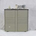
The General Radio 1422-N Precision Capacitor was introduced in Catalog Q (1961) and remained available through Catalog U (1970).
It is a laboratory quality, precision variable capacitor specifically designed for RF applications, an updated design of the 722-N with an aluminum case and redesigned frequency control knob.
The set value can be read directly from a drum mounted on the rotor shaft. A correction chart is mounted on the panel for that particular capacitor.
The rotor is mounted on preloaded ball bearings in an aluminum casting, driven by a precision worm drive.
Specifications
- Capacitance Range 100 to 1150 pF
- Dial Accuracy: See Experimenter
- Maximum Voltage: 1000 V peak
Links
| Two-Terminal | Three-Terminal |
|---|---|


