722-D: Difference between revisions
(Created page with "Type '''722-D Precision Variable Capacitor'''. ==Specifications== ==Links== ==Photos== <gallery> </gallery> Category:Capacitance Standards") |
No edit summary |
||
| (6 intermediate revisions by 2 users not shown) | |||
| Line 1: | Line 1: | ||
{{GR Product | |||
|model=722-D | |||
|codes=CRUEL,CRUELQUATZ | |||
|class=capacitance standards | |||
|summary=Precision Capacitor | |||
|image=GR 722-D Close-up.jpg | |||
|caption=General Radio 722-D Precision Capacitor | |||
|series=722 | |||
|introduced=1936 | |||
|discontinued=1959 | |||
|designers= | |||
|manuals= | |||
* '''Manual Needed''' | |||
{{Catalog History}} | |||
}} | |||
The {{Title|General Radio 722-D Precision Capacitor}} was introduced in {{Catalog J}} and remained available through {{Catalog P}}. | |||
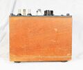
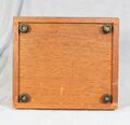
The Type 722-D is a laboratory quality, dual section, precision variable capacitor. The capacitor is supplied with a wooden carrying case fitted. | |||
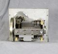
A direct reading of both sections is obtained from a drum mounted on the rotor shaft. | |||
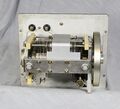
The rotor is mounted on ball bearings in an aluminum casting driven by a precision worm drive, and is electrically attached to the frame with silver overlay contacts. | |||
The two stators are brought out to separate terminals on the panel with the shared rotor terminal. The rotor terminal is a the same potential as the panel and copper-lined walnut case. | |||
A correction chart is mounted on the panel for that particular capacitor. | |||
==Specifications== | ==Specifications== | ||
* '''Capacitance Range''' 25 to 100 pF and 100 to 1100 pF | |||
* '''Dial Accuracy:''' High Range ±1 pF ±0.1%; Low Range ±0.2 pF ±0.1% | |||
* '''Maximum Voltage:''' 1000 V peak | |||
==Links== | ==Links== | ||
* [[Media:GR Exp 722-D 02_1937.pdf|Experimenter February 1937 describing Types 722]] | |||
* [[Media:GR Exp 722 01-1938.pdf|Experimenter January 1938 describing Types 722]] | |||
* [[Media:GR Exp 722 10_1938.pdf|Experimenter October 1938 describing Types 722]] | |||
{{722 Series}} | |||
==Photos== | ==Photos== | ||
<gallery> | <gallery> | ||
GR 722-D Front.jpg | |||
GR 722-D Top.jpg | |||
GR 722-D Bottom.jpg | |||
GR 722-D Rear.jpg | |||
GR 722-D Case Inside.jpg | |||
GR 722-D Inside Bottom.jpg | |||
GR 722-D Inside Left.jpg | |||
GR 722-D Inside Top.jpg | |||
GR 722-D Interior Right.jpg | |||
GR 722-D Interior.jpg | |||
GR 722 Carrying Case Front.jpg|Carrying Case | |||
GR 722 Carrying Case Inside.jpg|Carrying Case | |||
GR-722-D-1.jpg | |||
</gallery> | </gallery> | ||
[[Category:Capacitance Standards]] | [[Category:Capacitance Standards]] | ||
Latest revision as of 01:54, 4 May 2024
The General Radio 722-D Precision Capacitor was introduced in Catalog J (1936) and remained available through Catalog P (1959).
The Type 722-D is a laboratory quality, dual section, precision variable capacitor. The capacitor is supplied with a wooden carrying case fitted.
A direct reading of both sections is obtained from a drum mounted on the rotor shaft.
The rotor is mounted on ball bearings in an aluminum casting driven by a precision worm drive, and is electrically attached to the frame with silver overlay contacts.
The two stators are brought out to separate terminals on the panel with the shared rotor terminal. The rotor terminal is a the same potential as the panel and copper-lined walnut case.
A correction chart is mounted on the panel for that particular capacitor.
Specifications
- Capacitance Range 25 to 100 pF and 100 to 1100 pF
- Dial Accuracy: High Range ±1 pF ±0.1%; Low Range ±0.2 pF ±0.1%
- Maximum Voltage: 1000 V peak
Links
- Experimenter February 1937 describing Types 722
- Experimenter January 1938 describing Types 722
- Experimenter October 1938 describing Types 722
- 722-D
- 722-N
- 722-NQ
Photos
-
-
-
-
-
-
-
-
-
-
-
Carrying Case
-
Carrying Case
-


