1214-D: Difference between revisions
No edit summary |
No edit summary |
||
| Line 32: | Line 32: | ||
==Links== | ==Links== | ||
* [[1214-AS2]] – electrically identical | |||
* [[Media:GR Exp 1214-AS2 08_1956.pdf|Experimenter August 1956 describing Type 1214-AS2]] | * [[Media:GR Exp 1214-AS2 08_1956.pdf|Experimenter August 1956 describing Type 1214-AS2]] | ||
* [[Media:GR Exp 1214-D 07_1958.pdf|Experimenter July 1958 describing Type 1214-D]] | * [[Media:GR Exp 1214-D 07_1958.pdf|Experimenter July 1958 describing Type 1214-D]] | ||
Revision as of 06:57, 30 April 2024
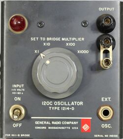
The General Radio 1214-D Unit Oscillator was introduced in Catalog P (1959) and remained available through Catalog S (1965).
The Type 1214-D is a unit oscillator specifically designed as a generator for the Type 1611-B Capacitance Test Bridge. It operates at 120 Hz, the recommended frequency for testing electrolytic capacitors.
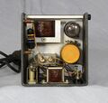
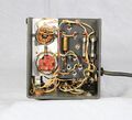
The 1214-D output circuit uses two transformers, the first serving as a load for the oscillator tube, and the second acting as an adjustable match for the Type 1611-B bridge. A front-panel phone jack acts as an input to the matching transformer for an external oscillator.
A single 117N7 tube contains the power supply rectifier and a beam PA as the oscillator. A Thyrite element (varistor) is used in the 117N7 grid circuit to limit oscillator amplitude. Like other instruments in the 1214 family (1214-M, 1214-A, and 1214-E), the 1214-D's power supply is transformerless.
Specifications
- Frequency: 120 cycles ±2%
- Output Impedance: Four impedances to match the impedance of the Type 1611-B Capacitance Test Bridge at four multiplier positions
- Output: At least 2000 mW into matched load
- Distortion: Less than 3% into a matched load
Links
- 1214-AS2 – electrically identical
- Experimenter August 1956 describing Type 1214-AS2
- Experimenter July 1958 describing Type 1214-D
- General Radio 1611-B Manual


